Disaster tolerance method, network element and server

A network element and disaster recovery technology, applied in electrical components, wireless communication, transmission systems, etc.

Active Publication Date: 2016-05-18
ZTE CORP
View PDF13 Cites 13 Cited by
  • Summary
  • Abstract
  • Description
  • Claims
  • Application Information

AI Technical Summary

Problems solved by technology

[0004] However, existing detection methods for Session Border Controller (SBC, SessionBorderController) and/or P-CSCF faults will generate a large amount of wireless connection establishment and release signaling, thus bringing

Method used


Image

  • Disaster tolerance method, network element and server
  • Disaster tolerance method, network element and server
  • Disaster tolerance method, network element and server

Examples


Embodiment 1

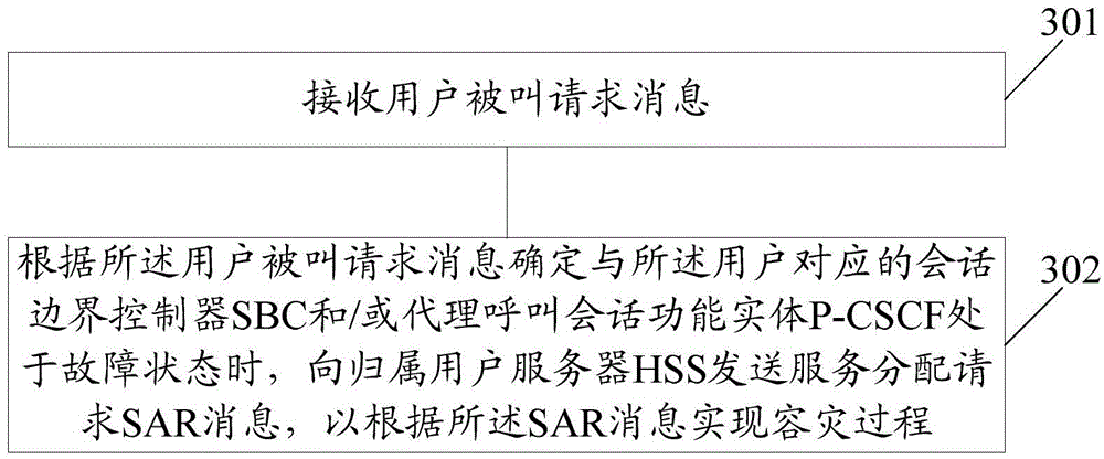
[0083] image 3 It is a schematic diagram of the implementation process of the disaster recovery method in the embodiment of the present invention Figure 1 ; The method is applied to the S-CSCF network element side; image 3 As shown, the method includes:

[0084] Step 301: receiving a call request message from a user;

[0085] Step 302: When determining that the SBC and / or P-CSCF corresponding to the user is in a fault state according to the user called request message, send a service assignment request (SAR, Server-Assignment-Server) to a home subscriber server (HSS, HomeSubscriberServer) Request) message, to realize the disaster recovery process according to the SAR message;

[0086] Wherein, the SAR message carries the P-CSCF disaster recovery identifier.

[0087] In the above solution, when it is determined according to the user called request message that the SBC and / or P-CSCF corresponding to the user is in a fault state, sending a SAR message to the HSS includes: ...

Embodiment 2

[0122] Figure 5 It is a schematic diagram of the implementation process of the disaster recovery method in the embodiment of the present invention Figure II ; The method is applied to the HSS side, such as Figure 5 Said, said method comprises:

[0123] Step 501: Receive a SAR message; wherein, the SAR message is generated by an S-CSCF network element according to a user called request message; the SAR message carries a P-CSCF disaster recovery identifier.

[0124] In this embodiment, the SAR message is generated when the S-CSCF receives the called request message from the user and determines that the active SBC and / or P-CSCF corresponding to the user is faulty.

[0125] In the above scheme, the method also includes:

[0126] According to the SAR message, when determining that the MME and / or SGSN corresponding to the user supports the disaster recovery function indicated by the P-CSCF disaster recovery identifier, generate an SAA message;

[0127] sending the SAA message...

Embodiment 3

[0150] The embodiment of the present invention also provides a disaster recovery method, the method is applied to the MME and / or SGSN side; the method includes:

[0151] receiving an IDR message; the IDR message carries a P-CSCF disaster recovery identifier;

[0152] According to the P-CSCF disaster recovery identifier in the IDR message, implement a deactivation or detachment network procedure corresponding to the user, so that the user equipment corresponding to the user can re-establish a network connection.

[0153] In order to implement the above method, an embodiment of the present invention further provides a second network element, where the second network element includes:

[0154] The third receiving unit is configured to receive an insert user data request IDR message; the IDR message carries a proxy call session function entity P-CSCF disaster recovery identifier;

[0155] A service implementation unit, configured to implement the deactivation or detachment networ...


PUM


Abstract

An embodiment of the invention discloses a disaster tolerance method which is applied to a serving-call session control function S-CSCF network element side. The method comprises the following steps: receiving a user called request message; and when determining that a session border controller SBC and/or a proxy-call session control function P-CSCF corresponding to the user are/is in a state of failure according to the user called request message, sending a server assignment request SAR message to a home subscriber server HSS so as to implement a disaster tolerance process according to the SAR message, wherein the SAR message carries a P-CSCF disaster tolerance identifier. Other embodiments of the invention disclose a network element and a server.

Description

technical field [0001] The present invention relates to a proxy call session function entity (P-CSCF, Proxy-CallSessionCallFunction) disaster recovery technology, in particular to a disaster recovery method, a network element and a server. Background technique [0002] The Internet Protocol Multimedia Subsystem (IMS, IPMultimediaSubsystem) is the development direction of future multimedia communication, and it is also the most important part of the next generation network. The IMS is a subsystem that supports Internet Protocol (IP, Internet Protocol) multimedia services proposed by the Third Generation Partnership Project (3GPP, Third Generation Partnership Project). The notable feature of the IMS is that it adopts the Session Initiation Protocol (SIP, SessionInitialProtocol) system, Make the communication independent of the access mode, so as to realize the functions of separating the control function and bearing capacity of various multimedia services, separating the call ...

Claims


Application Information

Patent Timeline
IPC IPC(8): H04W24/04
CPCH04L41/00
Inventor 赵文贤陶运锋
Owner ZTE CORP
Why Eureka
Try Eureka