Bodily worn multiple optical sensors heart rate measuring device and method

An optical sensor and measurement value technology, applied in the field of wearable heart rate sensors, can solve problems such as unwanted noise, inaccurate heart rate, and affecting sensitivity

Inactive Publication Date: 2016-05-18
LIFEBEAM TECH
View PDF6 Cites 11 Cited by
  • Summary
  • Abstract
  • Description
  • Claims
  • Application Information

AI Technical Summary

Problems solved by technology

[0008] In the embodiments of the present invention, the problem that the actuation of the PPG sensor may cause undesirable noise and inaccurate heart rate measurement and affect the sensitivity is solved

Method used


Image

  • Bodily worn multiple optical sensors heart rate measuring device and method
  • Bodily worn multiple optical sensors heart rate measuring device and method
  • Bodily worn multiple optical sensors heart rate measuring device and method

Examples


Embodiment Construction

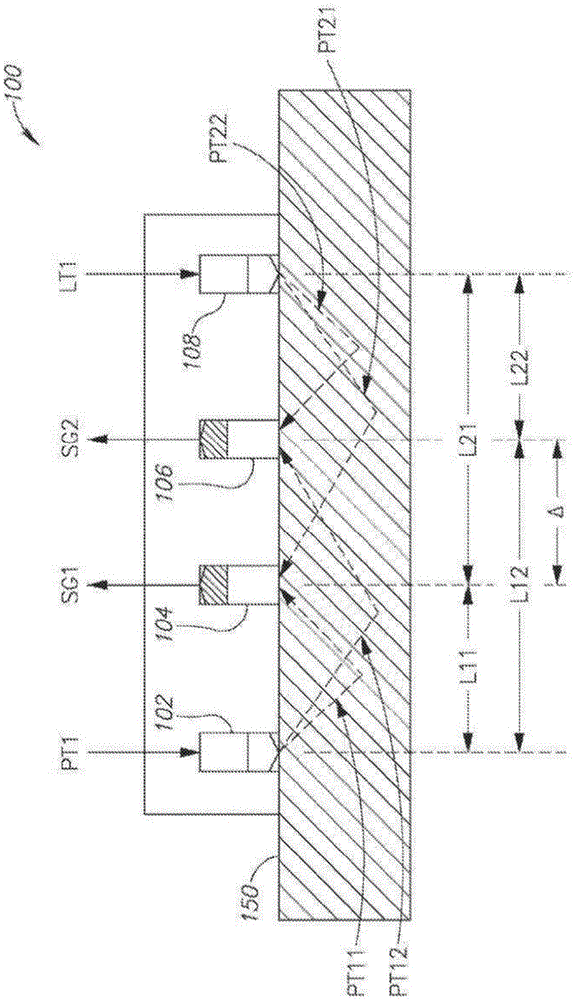
[0022] With reference to the detailed description and accompanying drawings, it is emphasized that the particulars shown are for purposes of illustration only and for the purpose of discussing the preferred embodiment of the invention and providing what are believed to be most useful and accurate in presenting the principles and concepts of the invention. Easy to understand description. In this respect, no attempt has been made to show the structural details of the invention in more detail, but rather the essential basic structure of the invention has been described. The content of the present invention described by several forms of specific embodiments shown in the drawings and in the description enables those skilled in the art to embody the present invention.

[0023] Before explaining the embodiments of the present invention in detail, it should be understood that the detailed component configurations and structures in the embodiments of the present invention and the drawi...


PUM


Abstract

A Photoplethysmography-based sensor for measuring heart rate is provided herein. The sensor may include a first light source and a second light source configured to illuminate a body tissue by a first light and a second light respectively; and a first and a second light detectors, each configured to detect light comprising portions of said first light and of said second light, transferred through the body tissue; and a processor with an analog measurement part configured to: receive light intensity readings of at least a portion of light as sensed by each one of both sensors and coming from each one of both sources; and calculate a measure of tissue absorption based on ratios of light portions transmitted by each one of both sources and measured by each one of both detectors.

Description

technical field [0001] The invention relates to a body-worn heart rate sensor, in particular to a sensor based on photoplethysmography. Background technique [0002] Before the related art is discussed, it may be helpful to clarify the definitions of certain terms that will be used below. [0003] As used herein, the term "light source" may include any component that emits light of a desired intensity and wavelength, such as a light emitting diode (LED), and the term light detector may include any component capable of detecting and measuring said A component that emits light from an object light source, such as a light-emitting diode or a phototransistor. Typically, the desired wavelength of the light source is in the range of 350-1100 nanometers. [0004] The term "photoplethysmography" or "PPG" as used herein is defined as the analysis of physiological parameters of an organ by utilizing the traces of transmitted light of the organ tissue. [0005] The term "reflected p...

Claims


Application Information

Patent Timeline
Patent Type & Authority Applications(China)
IPC IPC(8): A61B5/02A61B5/024
CPCA61B5/6803A61B5/6844A61B5/7214A61B5/02438A61B5/6814A61B2562/0219A61B2562/043A61B5/02427
Inventor 优素福·甘德尔曼兹维·欧朗约阿夫·阿明诺夫奥马里·约夫罗伊·罗兹尼曼乔纳森·阿帕斯欧夫
Owner LIFEBEAM TECH
Why Eureka
Try Eureka