Boiling cavity type radiator

A heat dissipation device and boiling chamber technology, applied in cooling/ventilation/heating transformation, instruments, electrical digital data processing, etc., can solve the problems of heating element 20 temperature rise, boiling fluid oscillating contact, and inability to ensure heat transfer function, etc., to achieve Easy processing, fewer components, and simple structure

Inactive Publication Date: 2006-06-07
HONG FU JIN PRECISION IND (SHENZHEN) CO LTD +1
View PDF0 Cites 10 Cited by
  • Summary
  • Abstract
  • Description
  • Claims
  • Application Information

AI Technical Summary

Problems solved by technology

[0010] Since the heating area of ​​the high-heat flux heating element 20 is usually smaller than the bottom area of ​​the cavity 10', the fluid will be violently stirred in the boiling area in contact with the heating area, resulting in a gap between the cooling surface of the top cover of the cavity and the boiling fluid. The periodic density wave (density wave) is caused in between, which causes the boiling fluid to vibrate and contact on the heat dissipation surface, thus forming a discontinuous and intermittent condensation heat transfer mode that is not conducive to stable heat transfer, seriously affecti...

Method used


Image

  • Boiling cavity type radiator
  • Boiling cavity type radiator
  • Boiling cavity type radiator

Examples


Embodiment Construction

[0043] The present invention will be further described below in conjunction with the embodiments with reference to the accompanying drawings.

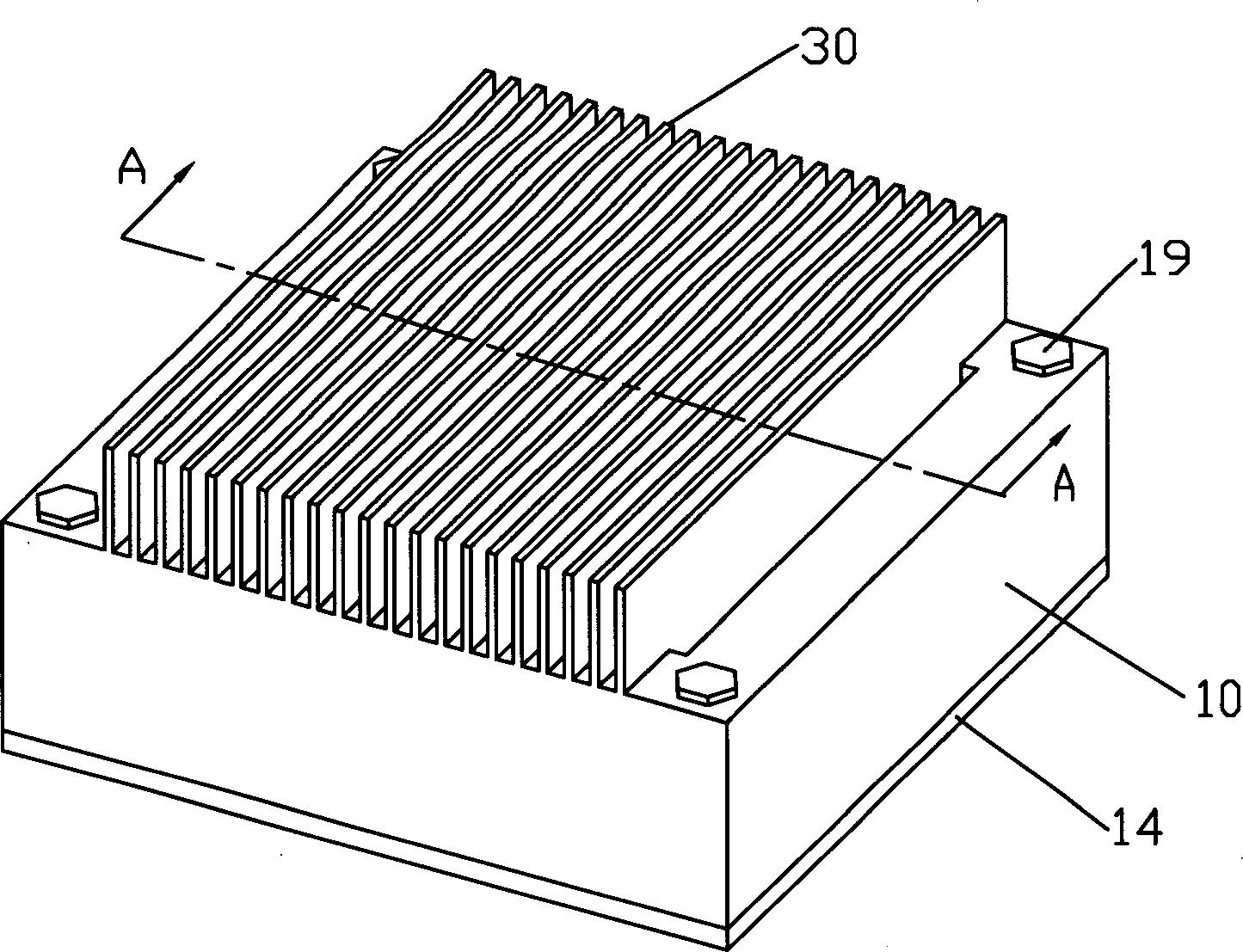
[0044] see Figure 3 to Figure 16 As shown, the boiling chamber heat sink of the present invention is used to be installed on a heating element 20 such as a central processing unit to dissipate heat.

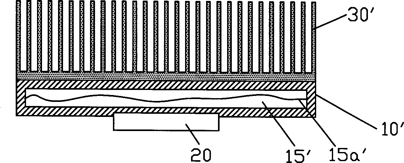
[0045] image 3 It is a three-dimensional schematic diagram of the first embodiment of the boiling chamber heat sink of the present invention; Figure 4 for the reason image 3 In the cross-sectional view of the A-A section, the device includes a sealed cavity 10 and a heat dissipation fin 30 that is in close contact with the top of the cavity 10, and the bottom of the cavity 10 is in close contact with the heating element 20; wherein the cavity 10 is used for Accommodating the working fluid 15 that absorbs heat from the heating element 20 and produces a phase change, it is composed of a top cover 11, a side frame 12, and a heat-absor...


PUM


Abstract

A fluidizing cavity radiation device includes a sealed cavity containing working fluid and a radiation piece set on the top of the cavity, in which, the sealed cavity includes an absorption base plate and a top cover, said base plate is set with an intensifying device for heat conduction inside of the cavity including several absorption units, the top cover is for transmitting heat from the radiation surface of the top of the inside wall of the cavity to outside, a side frame is set downward around the edge of the cover to connect to the heat absorption base plate and the cover in sealing and a curved buffer space is formed between the surrounding of the cover and the side frame.

Description

【Technical field】 [0001] The invention relates to a heat dissipation device, in particular to a boiling chamber type high-efficiency heat dissipation device. 【Background technique】 [0002] With the continuous development of the electronic information industry, high-tech electronic products are conducive to the trend of thinner, thinner, multi-functional, and faster operation. However, the heat released by electronic components (especially the central processing unit) per unit area (heat flux) There are also more and more, leading to further development must face the bottleneck of how to reduce the operating temperature of electronic components. In order to make high-tech electronic products play their due functions, designing high-efficiency and light-weight heat sinks has become the next generation in the industry. Important challenges for advanced electronics. [0003] At present, in the field of heat dissipation of computer microprocessors, many heat dissipation devices...

Claims


Application Information

Patent Timeline
IPC IPC(8): H01L23/427G06F1/20H05K7/20
Inventor 刘泰健
Owner HONG FU JIN PRECISION IND (SHENZHEN) CO LTD
Why Eureka
Try Eureka