
Alignment method and alignment device

A reference, point-symmetrical technology, applied in the direction of measuring devices, optical devices, ion implantation plating, etc., can solve the problems of increased risk of damage, substrate damage, narrow camera field of view, etc.

Active Publication Date: 2016-05-18
CANON TOKKI CORP
View PDF3 Cites 15 Cited by
  • Summary
  • Abstract
  • Description
  • Claims
  • Application Information

AI Technical Summary

Problems solved by technology

[0005] However, the above-mentioned conventional alignment uses a high-magnification camera. As a result, the imaging field of view is narrow, and mask marks and substrate marks cannot be brought into the imaging field of view, resulting in poor alignment.
[0006] Furthermore, since the mask transfer accuracy is low, the position of the mask mark may not coincide with the imaging center of the camera set at a predetermined position during rough positioning, thereby reducing the alignment accuracy.
[0007] In addition, during rough positioning, since the rough positioning is performed by directly applying an external force to the substrate, if the edge of the contact position of the substrate stands up, the force will concentrate on one point of the contact edge, and the substrate may be damaged.
Especially for large substrates, due to the increase in self-weight, the force applied to one point increases, and the risk of damage increases
[0008] Furthermore, fragments of the damaged substrate adhere to the substrate or the like, thereby possibly causing a reduction in the production efficiency of the device

Method used


Image

  • Alignment method and alignment device
  • Alignment method and alignment device
  • Alignment method and alignment device

Examples


Embodiment 1

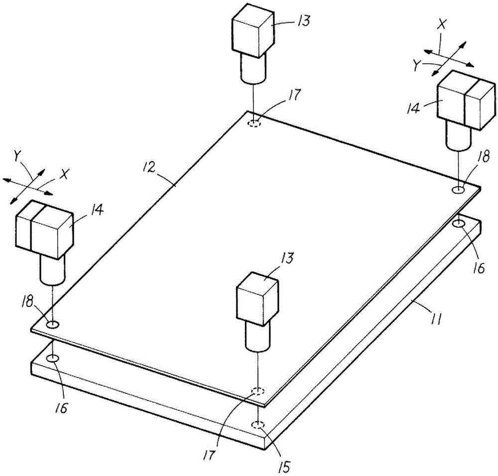
[0091] based on Figure 2 to Figure 5 A specific example 1 of the present invention will be described.

[0092] Embodiment 1 is an alignment device, which is provided in a film forming device to perform alignment between the mask 11 and the substrate 12, and the film forming device passes through the mask 11 The film forming material is deposited on the substrate 12 by the die opening to form a thin film on the substrate 12. The alignment device is provided in a processing chamber of a film forming device, such as a film forming chamber.

[0093] Specifically, Embodiment 1 has: a substrate moving unit that supports the substrate 12 and moves the substrate 12 in the X and Y directions; 15 and the third mark 17 for position detection on the substrate 12; the second imaging unit 14 has an imaging magnification higher than that of the first imaging unit 13, and the second mark 17 for position detection on the mask 11 16 and the fourth mark 18 for position detection provided on t...

Embodiment 2

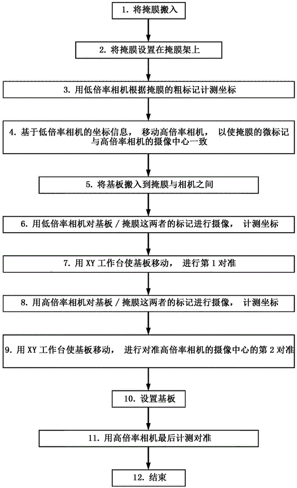
[0125] based on Image 6 A specific example 2 of the present invention will be described.

[0126] Embodiment 2 is an example of positioning the high-magnification camera 14 in the same manner as in Embodiment 1 using the third mark 17 and the fourth mark 18 of the substrate 12. In Embodiment 2, the same substrate moving unit as in Embodiment 1 is used. The mask moving unit of the structure moves the mask 11 along the X and Y directions for alignment.

[0127] In Example 2, alignment was performed in the following procedure.

[0128] A substrate holding step of holding the substrate 12 on the substrate rack is performed, a first imaging step of imaging the third marker 17 for position detection provided on the substrate 12 by the first imaging unit 13 is performed, and a first movement is performed. In the first moving step, the position information of the third marker 17 is obtained from the imaging data obtained in the first imaging step, and based on the position informat...


PUM


Abstract

Provided is an alignment method which is practically superior in capabilities for carrying out high precision alignment. When alignment of a substrate (12) and the mask (11) is carried out, a second imaging unit (14) with a high imaging magnification is positioned using imaging data imaged by a first imaging unit (13) with a low imaging magnification. Two stages of steps are carried out for positional correction for the substrate (12) and the mask (11) with the imaging range of the second imaging unit (14) as a reference: a first alignment step that is carried out using imaging data imaged by the first imaging unit (13), and a second alignment step that is carried out using imaging data imaged by the second imaging unit (14).

Description

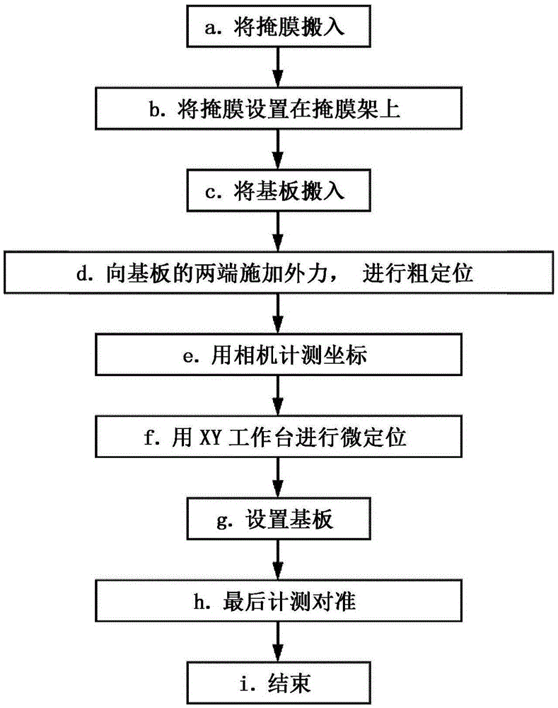
technical field [0001] The present invention relates to an alignment method and an alignment device. Background technique [0002] For example, the following alignment device is disclosed in the known patent document 1. The alignment device is provided in a film forming device to perform alignment between a mask and a substrate. A film-forming material is deposited on the substrate, thereby forming a thin film on the substrate. [0003] However, in recent years, higher-precision alignment is required, and a high-magnification camera is often used to image a mask mark and a board mark to perform alignment. Alignment using this high magnification camera is for example according to figure 1 The illustrated flow proceeds. [0004] Specifically, the mask is carried into the processing chamber (a.), the carried-in mask is set on the mask holder (b.), the substrate is carried into the processing chamber by a transport robot (c.), and the two ends of the substrate are Apply exte...

Claims


Application Information

Patent Timeline
IPC IPC(8): C23C14/04G01B11/00G03F9/00H01L21/027
CPCG03F9/7088C23C14/042G03F9/7038
Inventor 山根幸男石井博田中广树
Owner CANON TOKKI CORP
Learn More