Multipurpose combined harvester with three-link hitches on front portion and rear portion and devices matched with three-link hitches
A combine harvester, three-point suspension technology, applied in the direction of harvester, application, cutter, etc., can solve the problem that the combine harvester cannot be mounted on multiple operations procurement costs and other issues
- Summary
- Abstract
- Description
- Claims
- Application Information
AI Technical Summary
Problems solved by technology
Method used
Image

Examples
Embodiment 1
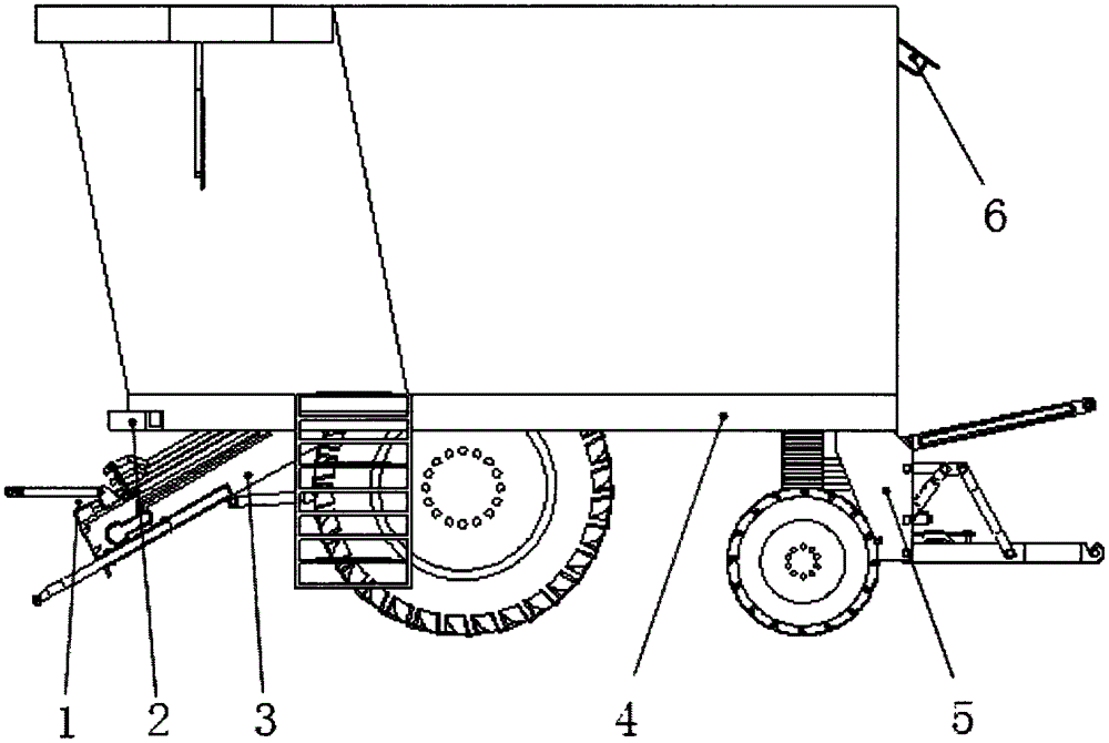
[0027] like figure 1 Shown, the multi-purpose combine harvester with three-point suspension device and its corollary device before and after, comprises header (not shown in the figure), crossing bridge 3 and frame 4, and the front portion or rear portion of combine harvester is respectively provided with The front three-point suspension device and its supporting device 1 and the rear three-point suspension device and its supporting device 5, the front part of the combine harvester frame is provided with a counterweight hanging iron frame 2 for hanging the counterweight iron to balance the combine The machine is heavy, and the rear of the combine harvester is equipped with a camera 6, which is connected to the display screen in the cab. Hand check the working status of the agricultural implements mounted on the rear of the combine harvester.
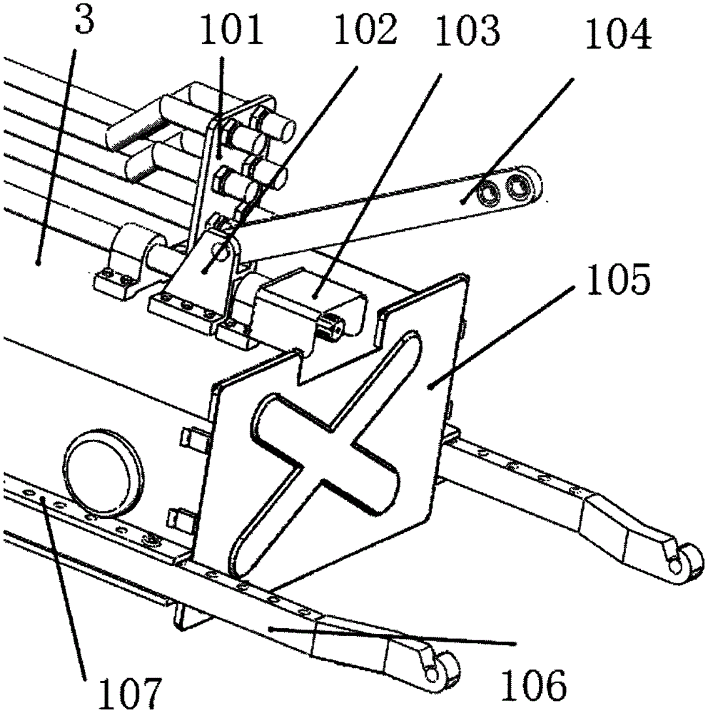
[0028] like figure 2 As shown, a structure of the front three-point suspension device and its corollary device includes: upper tie ro...
Embodiment 2
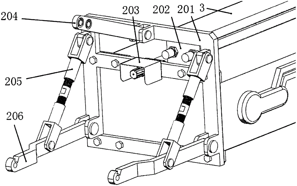
[0031] This embodiment is basically the same as Embodiment 1, the difference is that, as image 3 As shown, another structural schematic diagram of the front three-point suspension device and its supporting devices, including a mounting base 201, an upper tie rod 204 hingedly mounted on the mounting base 201, a lower rod 206 hingedly mounted on the mounting base 201, and a hinged connection lower rod 206 and the inclined rod 205 of the mounting base 201, the front power output shaft 203 driven by the transmission device installed on the mounting base 201, the front hydraulic output interface 202 installed on the mounting base 201 connected to the hydraulic pump through the hydraulic control valve, and the mounting base 201 is installed on the front end of bridge 3.
PUM
 Abstract
Description
Claims
Application Information
 - R&D
- Intellectual Property
- Life Sciences
- Materials
- Tech Scout
- Unparalleled Data Quality
- Higher Quality Content
- 60% Fewer Hallucinations
Browse by: Latest US Patents, China's latest patents, Technical Efficacy Thesaurus, Application Domain, Technology Topic, Popular Technical Reports.
© 2025 PatSnap. All rights reserved.Legal|Privacy policy|Modern Slavery Act Transparency Statement|Sitemap|About US| Contact US: help@patsnap.com