Propeller casting molding method

A casting molding and propeller technology, which is used in casting molding equipment, casting molds, casting mold components, etc., can solve the problems of long production time, long production time, and high labor intensity for a single piece, and can reduce the diameter and size of the propeller hub. Grinder workload and the effect of improving working conditions

Active Publication Date: 2016-05-25
WUHU FUJIHENG MACHINERY
View PDF10 Cites 13 Cited by
  • Summary
  • Abstract
  • Description
  • Claims
  • Application Information

AI Technical Summary

Problems solved by technology

[0002] The traditional ship propeller casting process mainly adopts base plane pitch surface scraper + external pitch triangle plate + sand filling plate + false blade, etc. Compared with the ship propeller casting method invented this time, it has the following disadvantages: 1. It is difficult for molders to operate High accuracy requirements
The pitch value of each point of the propeller blade is controlled by the scraper and the coordinate ruler, and the accuracy is affected by the precision of the tool, resulting in an increase in the thickness of the blade, increasing the workload of subsequent grinding, and prolonging the construction period; 2. The shapers are labor intensive and have many processes. Poor working conditions; 3. It takes a long time to make a single piece. Due to many processes and high labor intensity, it leads to low efficiency and long production time, which restricts the improvement of the quality and efficiency of ship propellers and forces us to adopt new processes and methods that are more suitable for the market. Production of ship propellers

Method used


Image

  • Propeller casting molding method
  • Propeller casting molding method
  • Propeller casting molding method

Examples


Embodiment Construction

[0035] The specific implementation manner of the present invention will be described in further detail below by describing the embodiments with reference to the accompanying drawings.

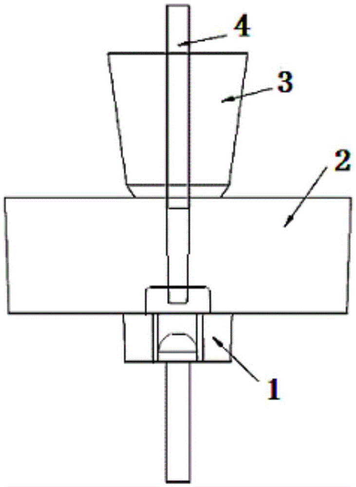
[0036] The propeller casting molding method of the present invention, the propeller casting gating system that adopts, as figure 1 As shown, including the propeller sand core 2, the propeller sand core 4 vertically passes through the center of the propeller sand core 2, and forms a cavity with the propeller sand core 2 for forming the propeller in the propeller sand core 2, and the upper end of the propeller sand core 2 is connected to the riser 3. The lower end is connected to the tile gate sand core 1 for drainage. In the present invention, the propeller sand core 2 is assembled from a plurality of independent blade sand cores.

[0037] When making the blade sand core, install the paddle steel mold on the shell molding machine, align the sand blasting port of the shell molding machine, contr...


PUM


Abstract

The present invention discloses a propeller casting molding method comprising the following steps: making a propeller steel mold; making a sand core; assembling for forming a propeller sand core; making a pouring gate steel mold; making a mud core; and making a sand box; and the manufacturing process comprises casting; picking up; sawing a riser, and grinding for molding. The propeller casting molding method is strong in operability and good in technology, and can improve propeller quality, increase production efficiency and reduce production costs, product quality meets customer demand for products, and a new profit growth point is created for enterprises.

Description

technical field [0001] The invention belongs to the technical field of ships, and more specifically relates to a propeller casting method. Background technique [0002] The traditional ship propeller casting process mainly adopts base plane pitch surface scraper + external pitch triangle plate + sand filling plate + false blade, etc. Compared with the ship propeller casting method invented this time, it has the following disadvantages: 1. It is difficult for molders to operate Accuracy requirements are high. The pitch value of each point of the propeller blade is controlled by the scraper and the coordinate ruler, and the accuracy is affected by the precision of the tool, resulting in an increase in the thickness of the blade, increasing the workload of subsequent grinding, and prolonging the construction period; 2. The shapers are labor intensive and have many processes. Poor working conditions; 3. It takes a long time to make a single piece. Due to many processes and high...

Claims


Application Information

Patent Timeline
Patent Type & Authority Applications(China)
IPC IPC(8): B22C9/22B22C9/10B22C9/06B22D17/22
CPCB22C9/061B22C9/103B22C9/22B22D17/22B22D17/2209
Inventor 陈殷舫陶红胡宗元管仲曹艳贝刘金明庄南海沈思强吴琴
Owner WUHU FUJIHENG MACHINERY
Why Eureka
Try Eureka