
Method and device for automatically setting tool correction value of machine tool

An automatic setting and correction value technology, applied in the direction of automatic control devices, feeding devices, manufacturing tools, etc., can solve problems such as costing a lot of effort and time, changing tool correction values, etc., to reduce the workload, prevent operating errors, prevent The effect of typos

Inactive Publication Date: 2016-05-25
NAKAMURATOME SEIMITSU IND
View PDF14 Cites 19 Cited by
  • Summary
  • Abstract
  • Description
  • Claims
  • Application Information

AI Technical Summary

Problems solved by technology

[0010] In a machine tool that uses multiple tools for processing, such as a turret lathe, multiple tools, such as 8 or 12, are installed on one tool holder (turret), sometimes on one tool installation position (tool station) Two tools with different tool nose directions are installed, so there is a problem that it takes a lot of work and time to manually set the tool correction value in the controller for these tools
Also, these tools are mounted on the turret through the tool holder, so even for the same tool, the tool correction value will change depending on the shape and size of the tool holder used

Method used


Image

  • Method and device for automatically setting tool correction value of machine tool
  • Method and device for automatically setting tool correction value of machine tool
  • Method and device for automatically setting tool correction value of machine tool

Examples


Embodiment Construction

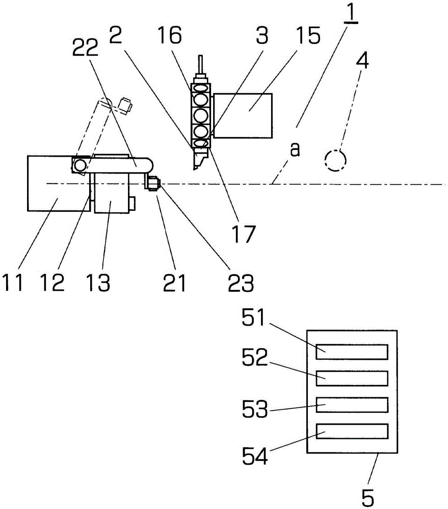
[0036] Hereinafter, embodiments of the present invention will be described by taking an NC turret lathe having a basic structure as an example. The NC turret lathe has a machine body 1 and a controller 5 . The machine main body 1 has a tool post 15 and a spindle 12 supported by a headstock 11 fixed to a bed. A jig 13 for holding a workpiece is attached to the front end of the spindle 12 . The tool holder 15 is a turret tool holder with a turret 16 . A plurality of knives 2 are attached to the turret 16 via holders 3 . The tool post 15 can freely move and locate in the Z-axis direction and the X-axis direction according to the instructions from the controller 5, wherein the Z-axis direction is the direction of the spindle axis a, and the X-axis direction is perpendicular to the Z-axis direction and is parallel to the spindle axis. The direction in which the axis a approaches or departs from.

[0037] A tool setter 21 and its advancing and retreating device 22 are installed ...


PUM


Abstract

The invention provides a method and device for automatically setting tool correction value of machine tool, which can automatically set a tool correction value for a plurality of tools attached to a tool post of a NC machine tool (a relative positional relation between a tool post and a cutting edge of the tool). An image (A) of a tool (2) attached to a tool post (15) is acquired by a camera (4) installed inside a machine tool, the position and the direction of a cutting edge (24) of the tool (2) on the image are obtained, and a tool correction value is automatically set in a controller while being obtained from a positional relation between the installation position of the camera (4) and the position of the tool post (15) when the image is acquired. The tool correction value set by the controller (5) can be measured by a tool setter (21). In this case, a false tool correction value is obtained from the image, the cutting edge (24) of the tool is detected by a detection sensor (23) of the tool setter (21), and a correction value setting program (53) registered in the controller (5) is automatically executed.

Description

technical field [0001] The present invention relates to a method and a device for automatically setting the relative positional relationship between a tool rest of an NC machine tool and the tip of a tool mounted on the tool rest. Background technique [0002] The machining shape of a workpiece (object to be processed) produced by a machine tool is determined by how the tip of the tool is moved relative to the workpiece. On the other hand, what the controller of the machine tool controls is the relative positional relationship between the workpiece and the tool holder on which the tool is installed. [0003] A variety of cutting tools corresponding to the processing types are installed on the tool holder. Depending on the tool, the length and direction from the tool holder to the tool tip are different. Therefore, only the positional relationship from the reference position of the tool holder (the position recognized and controlled by the controller) to the tool tip is pre-...

Claims


Application Information

Patent Timeline
IPC IPC(8): B23Q15/24B23Q17/22
CPCB23Q15/24B23Q17/2208B23Q17/2225B23Q17/2233B23Q17/2428G05B19/404G05B2219/37559G05B2219/50135G05B2219/50291
Inventor 西村尚贡
Owner NAKAMURATOME SEIMITSU IND
Learn More