Two-motor driven variable-stiffness elastic joint of robot

A technology driven by dual motors and elastic joints, applied in manipulators, manufacturing tools, joints, etc., can solve the problems of inability to achieve linearly adjustable stiffness characteristics, waste of stiffness adjustment motor power, and inability to adjust stiffness, etc., to improve energy utilization The effect of high efficiency, elimination of mechanical shock, and fast real-time response

Inactive Publication Date: 2016-05-25
SOUTH CHINA UNIV OF TECH
View PDF12 Cites 12 Cited by
  • Summary
  • Abstract
  • Description
  • Claims
  • Application Information

AI Technical Summary

Problems solved by technology

After searching the existing technical literature, it is found that most of the existing public series elastic drive joints do not have the function of stiffness adjustment. For example, Yang Qizhi of Jiangsu University proposed a soft elastic joint based on Archimedes spiral elastic body , Patent Publication No. CN105082170A, the elastic body adopts two circular spring pieces, and there are Archimedes spiral grooves on the spring pieces to increase the flexibility of the joint. Although the device is compact in structure, the range of motion is limited and the stiffness cannot be adjusted.
Even if there are very few spring devices with stiffness adjustment at present, there are still problems such as low integration, cumbersomeness, and poor versatility. For example, a robot joint with variable stiffness proposed by Huang Qiang et al. of Beijing Institute of Technology, patent Publication No. CN104440936A, a main friction plate and two secondary friction plates are installed on the joint, and the friction force is generated under the pre-tightening force of the bolts. The friction characteristics of the friction plates are used to adjust the stiffness, but the friction plates are consumables. It will lose its original function after a period of time and needs to be replaced regularly, and it only has two levels of stiffness adjustment, which cannot achieve linearly adjustable stiffness characteristics
More importantly, the currently disclosed stiffness-adjustable flexible joints all use one motor to drive the joint, and another motor to adjust the stiffness instead of driving the joint, which wastes the power of the stiffness-adjusting motor; and if a low Performance stiffness adjustment motor, it is difficult to ensure that the joint stiffness can be adjusted in time in the event of a collision

Method used


Image

  • Two-motor driven variable-stiffness elastic joint of robot
  • Two-motor driven variable-stiffness elastic joint of robot
  • Two-motor driven variable-stiffness elastic joint of robot

Examples


Embodiment Construction

[0022] The embodiments of the present invention are described in detail below. This embodiment is implemented on the premise of the technical solution of the present invention, and detailed implementation methods and specific operating procedures are provided, but the protection scope of the present invention is not limited to the following implementation example.

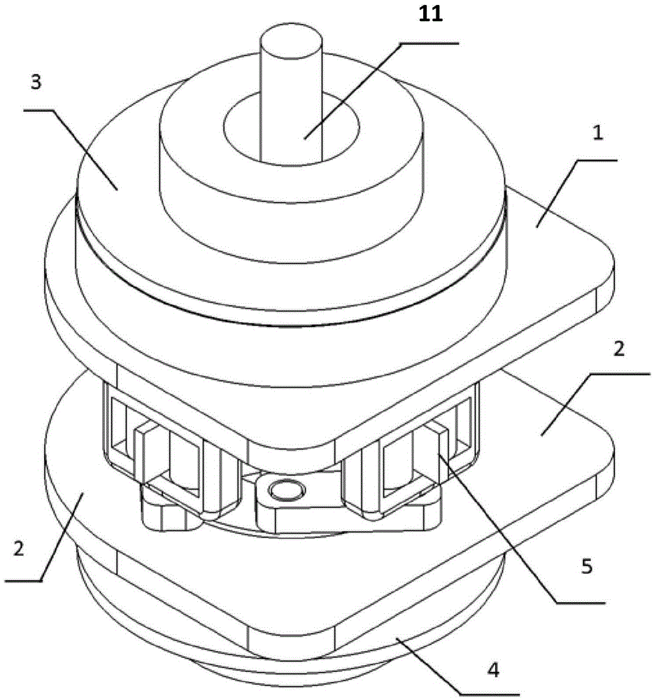
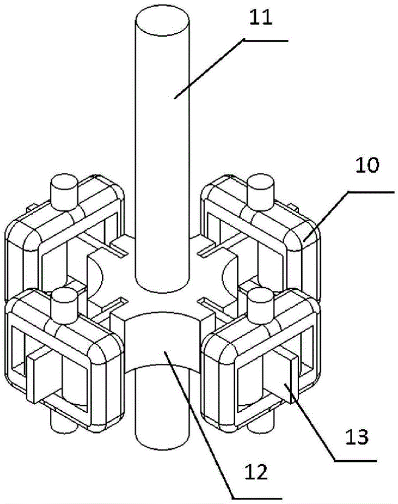
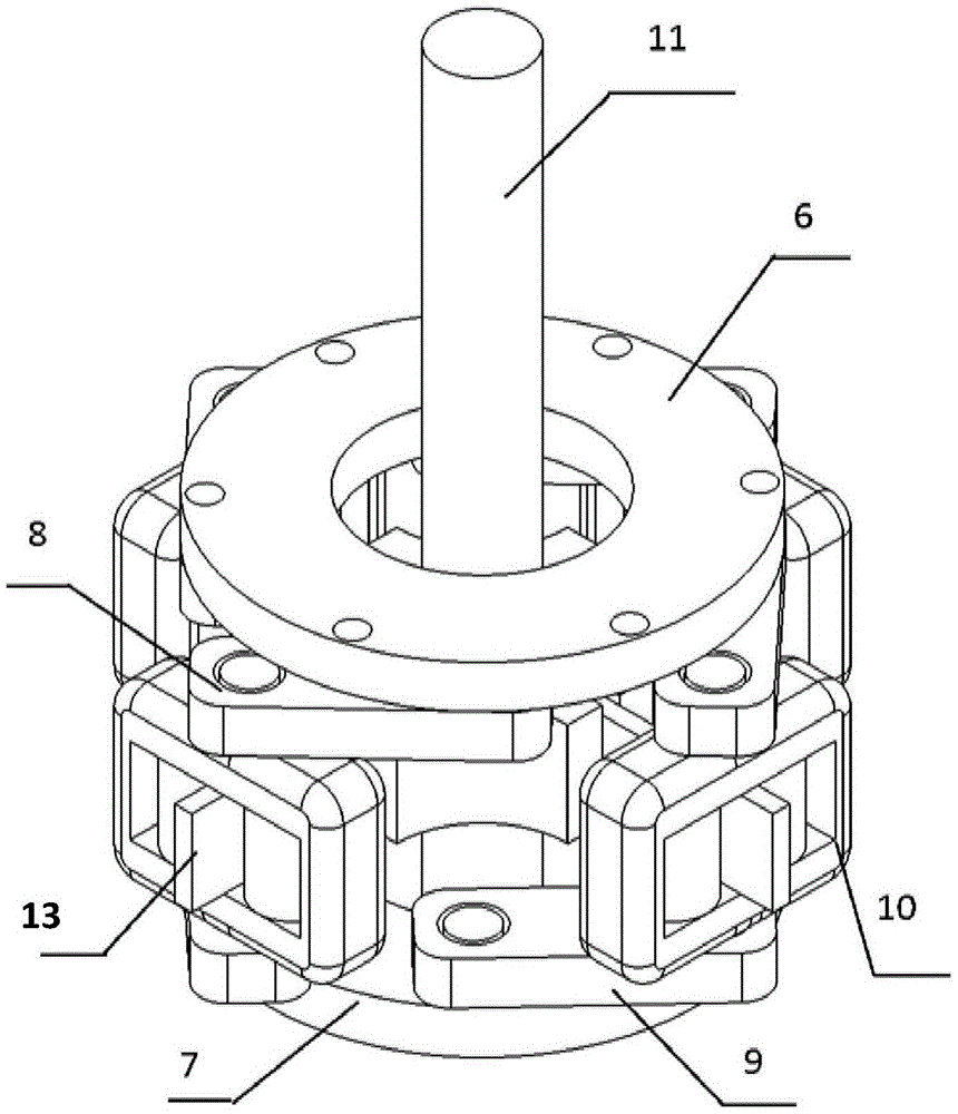
[0023] like Figure 1 to Figure 3 As shown, a dual-motor-driven robotic variable stiffness elastic joint includes an output shaft 11 located on the same axis of rotation, a flexible transmission mechanism 5, and a driving end. The driving end includes two coaxially driving connections connected to the flexible The hollow shaft drive motors at both ends of the transmission mechanism 5, the drive end also includes fixing plates respectively arranged at the two ends of the flexible transmission mechanism 5 for fixing two hollow shaft drive motor housings; the output shaft 11 and The middle part of the flexible transm...


PUM


Abstract

The invention discloses a two-motor driven variable-stiffness elastic joint of a robot. The two-motor driven variable-stiffness elastic joint comprises an output shaft, a flexible transmission mechanism and a driving end which are positioned on the same rotating axial line, wherein the driving end comprises two hollow shaft driving motors coaxially connected to two ends of the flexible transmission mechanism in a driving manner; the output shaft is fixedly connected with the middle part of the flexible transmission mechanism, and one end of the output shaft penetrates through and extends out of hollow shafts of the hollow shaft driving motors; under the impact of different loads on the output shaft, the two hollow shaft driving motors change an included rotation angle between the two motors to adjust the length of a force arm of the flexible transmission mechanism for driving the output shaft to rotate, thus adjusting the stiffness and realizing elastic buffering. The two-motor driven variable-stiffness elastic joint of the robot has the characteristics of high real-time response speed and high adjustment precision; the safety and the environment friendliness of the robot are improved; the two-motor driven variable-stiffness elastic joint is simple, portable, high in universality and wide in application range.

Description

technical field [0001] The invention relates to a robot bionic joint, in particular to a dual-motor-driven robot elastic joint with adjustable stiffness. The device is applicable to various joint-type robots and improves the safety and environmental friendliness of the robot. Background technique [0002] For a long time, the traditional robot joint design theory believes that the transmission mechanism with higher stiffness should be given priority to the mechanical connection mode between the power drive device and the joint hinge. Therefore, in the research of joint robots such as industrial robot arms, bionic multi-legged robots, and rehabilitation medical prostheses, the driving scheme of rigid connection between the motor output shaft and the joint mechanism is generally used. Its advantages lie in simple structure, precise positioning, and fast response. Meet the needs of various operations and applications. However, due to the lack of compliance of this driving sche...

Claims


Application Information

Patent Timeline
Patent Type & Authority Applications(China)
IPC IPC(8): B25J17/02
CPCB25J17/0258
Inventor 叶雯珺李智军彭芳章隆彬杨辰光
Owner SOUTH CHINA UNIV OF TECH
Why Eureka
Try Eureka