A plastic switch box integrated injection punching machine

A switch box and punching machine technology, applied in the direction of coating, etc., can solve the problems of punching machine damage, failure to knock out circular plastic plate waste, and circular plastic plate waste pushed to the initial stage, so as to reduce labor load, time-saving effect

Inactive Publication Date: 2017-08-08
CHENGDU CHUANXING TECH PLASTICS INDUSRTY CO LTD
View PDF7 Cites 0 Cited by
  • Summary
  • Abstract
  • Description
  • Claims
  • Application Information

AI Technical Summary

Problems solved by technology

All the above-mentioned steps are processed by specialized personnel. Therefore, when the factory produces the switch box that requires punching, it needs to invest a lot of manpower, material resources, and financial resources. The production cycle and product quality of external processing cannot be very fast. Good control and therefore a great influence on the production cost of the switch box
At the same time, there is also a great disadvantage in the punching step of this processing. The circular plastic plate waste after punching will either fall directly into the punching machine, which may cause damage to the punching machine and increase the trouble for workers to clean up. , or the card is very tight on the switch box, you need to knock hard to take out the round plastic plate when using it, causing some trouble
[0003] Therefore, some experts at home and abroad have conducted some research on the punching device of the plastic switch box, and have also designed some plastic plates that can be pushed back into the hole so that the operator can knock them off when they need to use them. Most of them failed to achieve the effect, and the circular plastic plate waste could not be pushed to the initial position, and there would always be large bumps, which were easy to fall off, or were not punched successfully, resulting in that the circular plastic plate waste could not be knocked open during use, and the switch box Not available

Method used


Image

  • A plastic switch box integrated injection punching machine
  • A plastic switch box integrated injection punching machine
  • A plastic switch box integrated injection punching machine

Examples


Embodiment

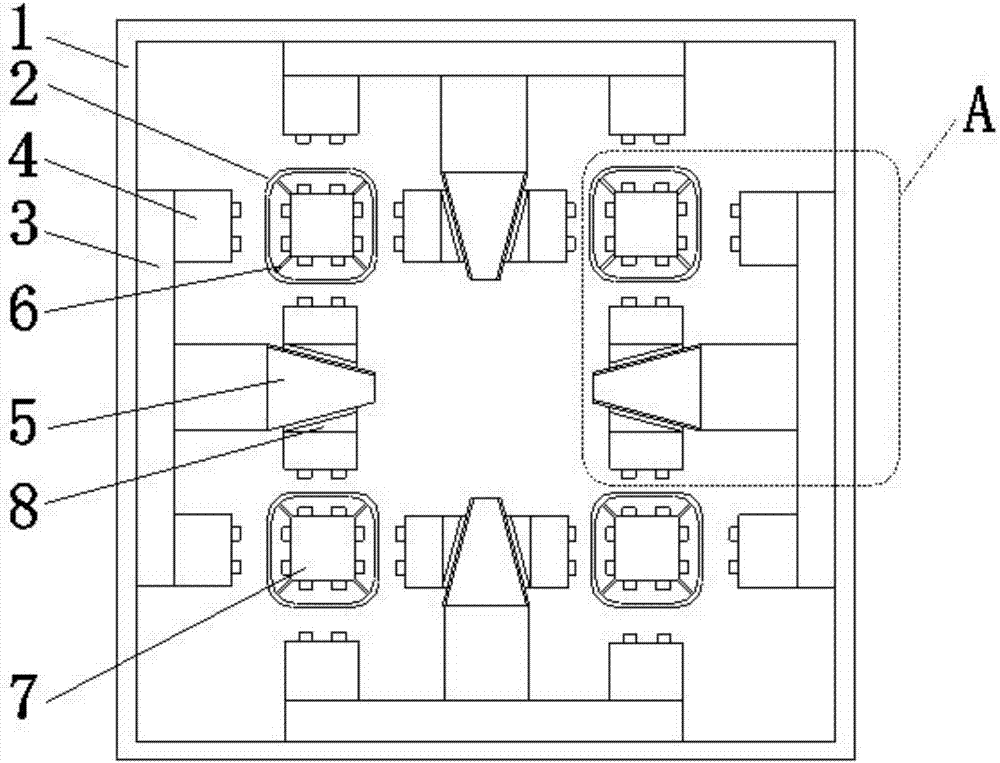
[0032] Such as figure 1 As shown, pour the PVC raw material powder into the heating plastic mixer, start the plastic switch box integrated injection punching machine, set the injection time, injection interval, punching frequency and other working parameters; flow the thermosetting plastic through the injection hole 6 to the In the injection mold, after it is cooled and formed, the side of the injection mold is raised to provide space for the next punching process;

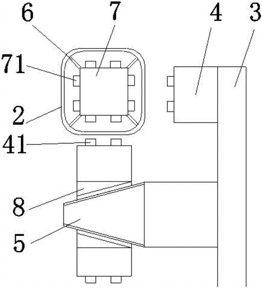
[0033] Such as figure 2 , image 3 As shown, the cylinder push plate 3 quickly pushes the punching knife rest 4 and the inclined plane push rod 5 forward, and the inclined plane of the inclined plane push rod 5 pushes the inclined plane knife rest holder 8 to move forward, and the punching blade 41 before the oil cylinder push plate 3 Punch out the hole 21 on the side of the switch box 2 with the punching blade 41 in front of the inclined knife rest holder 8 at the same time, so that it is evenly stressed on al...


PUM


Abstract

The invention relates to an integrated injection molding punching machine for a plastic switch box. The integrated injection molding punching machine comprises a chassis, an injection mold, a switch box, oil cylinder push plates, punching tool rests, a slope push rod, injection molding holes, a punching hole back-pushing device and a slope tool rest fixer, wherein the oil cylinder push plates are mounted at four edges of the chassis; the punching tool rests are mounted on the two sides of each of the oil cylinder push plates; the slope push rod is mounted in the middle of each of the oil cylinder push plates; the rear part of the slope tool rest fixer is in contact with the side wall of each of the oil cylinder push plates; the switch box is arranged in the injection mold inside the chassis; a vertical moveable device is arranged on the side wall of the injection mold; four injection molding holes are formed on the injection mold; the punching hole back-pushing device is arranged in the middle of the injection mold. According to the integrated injection molding punching machine for the plastic switch box, through the adjustment for mechanical structure, the products are automatically punched after injection molding and are once formed; the pitch of holes and hole depth after punching are kept consistent; the problems of waste falling, hole surface breaking and inconsistent hole depth of circular plastic plate are avoided; automatic control is adopted, no manual operation is required, time is saved and the workload of workers is reduced.

Description

technical field [0001] The invention relates to a device for manufacturing a plastic switch box, in particular to a plastic wire forming and punching equipment. Background technique [0002] In the current switch box production process, most of the injection molding and punching processing of the switch box are carried out separately. After the injection molding is completed, the formed switch box is transported to the punching machine, and the semi-finished switch box is placed on the punching machine by manpower. bit, carry out punching processing, and take out after processing. All the above-mentioned steps are processed by specialized personnel. Therefore, when the factory produces the switch box that requires punching, it needs to invest a lot of manpower, material resources, and financial resources. The production cycle and product quality of external processing cannot be very fast. Good control, therefore has a great influence on the production cost of the switch box...

Claims


Application Information

Patent Timeline
Patent Type & Authority Patents(China)
IPC IPC(8): B29C45/00
CPCB29C45/0055
Inventor 张岳岐李富彬曾贤东袁伟张道维侯英杰
Owner CHENGDU CHUANXING TECH PLASTICS INDUSRTY CO LTD
Why Eureka
Try Eureka