A material pneumatic conveying system with cleaning and collecting functions

A technology of pneumatic conveying and pneumatic transmission, applied in conveyors, transportation, packaging, packaging, etc., can solve the problems of increasing friction of objects to be conveyed, jamming of objects to be conveyed, high maintenance costs, and reducing the risk of breakage or blockage , Reduce the cost of use, the effect of high degree of automation

Active Publication Date: 2018-07-03
HUNAN SUNDY SCI & TECH DEV
View PDF12 Cites 0 Cited by
  • Summary
  • Abstract
  • Description
  • Claims
  • Application Information

AI Technical Summary

Problems solved by technology

[0005] (1) Affect the delivery efficiency
When there are foreign objects (residues) in the transmission pipeline or the packaging of the material to be transported is damaged and leaks into the transmission pipeline, these substances in the transmission pipeline will affect the normal operation of the material to be transported and seriously affect the delivery efficiency of the sample
[0006] (2) Difficult to clean and maintain
Since the pneumatic transmission pipeline is very long and very small (people cannot enter), it is very difficult to clean once foreign objects (residues) appear in the transmission pipeline
However, if it is not cleaned in time, it may cause the material to be transported to be stuck in the transmission pipeline. Once it is blocked, it will be more difficult to clean and dredge the pipeline, and the maintenance cost will be extremely high.
[0007] (3) Pipe wear is serious
Although it is possible that the object to be conveyed will push these foreign objects (residues) forward, because the transmission pipeline is very long, these foreign objects (residues) will increase the friction between the object to be conveyed and the inner wall of the transmission pipeline during the transportation process, resulting in Pipe wear is serious, the life of the transmission pipe is shortened, and the cost of use is increased

Method used


Image

  • A material pneumatic conveying system with cleaning and collecting functions
  • A material pneumatic conveying system with cleaning and collecting functions
  • A material pneumatic conveying system with cleaning and collecting functions

Examples


specific Embodiment 1

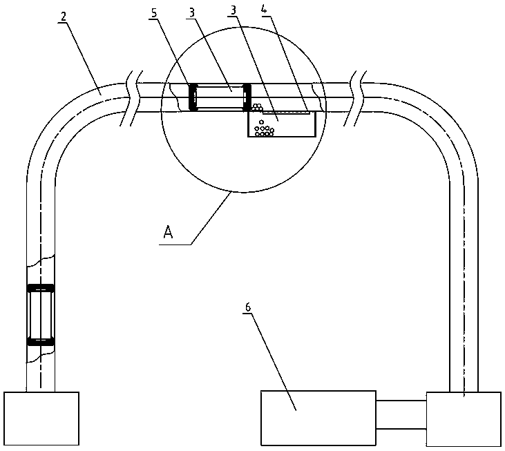
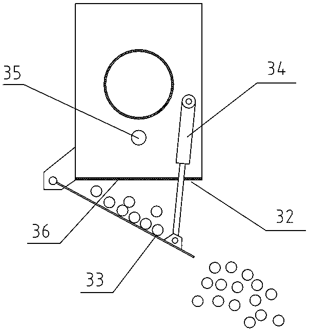
[0048] Specific embodiment 1: as Figure 6 As shown, in this embodiment, a sealing flange assembly 37 is provided at both ends of the falling material collecting device 3 , and the falling material collecting device 3 is sealingly connected with the pneumatic transmission pipeline 2 at both ends through the sealing flange assembly 37 . The foreign matter settling part 4 is set in the falling material collection device 3, and the pneumatic transmission pipeline 2 at both ends of the falling material collecting device 3 is kept in transmission connection through the foreign matter settling part 4, that is, the object to be transported 1 or the piston sheath 5 is transferred from the pneumatic transmission pipeline 2 at one end. Enter the falling material collection device 3, pass through the foreign matter settlement part 4 in the falling material collecting device 3, and then output from the falling material collecting device 3, and then enter the pneumatic transmission pipeline...

specific Embodiment 2

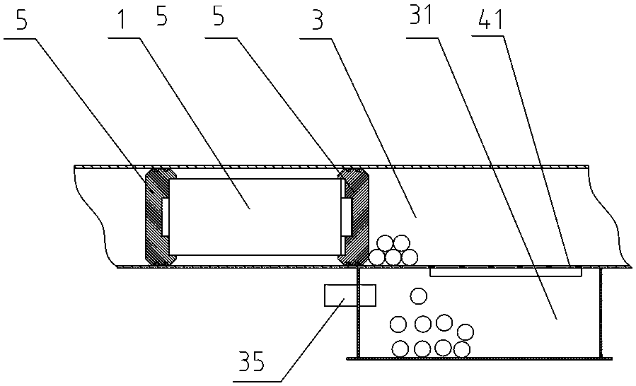
[0050] Specific embodiment 2: as Figure 7 As shown, in this embodiment, the falling material collection device 3 is arranged under the pneumatic conveying pipeline 2 , and the foreign matter settling part 4 is arranged on the bottom wall of the pneumatic conveying pipeline 2 . The top of the falling material collecting device 3 is provided with an opening. The staff does not need to disconnect the pneumatic transmission pipeline 2, but only needs to set the foreign matter settlement part 4 on the pipeline bottom wall of the pneumatic transmission pipeline 2 (a man-made one such as Figure 5 large-area settling holes 41 as shown, or use a Figure 4 The shown gasket with a plurality of settling holes 41 is placed on the opening of the bottom wall of the pneumatic transmission pipeline 2), and then the falling material collecting device 3 is sealed and fixed under the foreign matter settling part 4, so that the falling material collecting device 3 The top opening of the filter...

specific Embodiment 3

[0051] Specific embodiment 3: as Figure 8 As shown, in this embodiment, the falling material collection device 3 is arranged below the pneumatic transmission pipeline 2, and the foreign matter settlement part 4 is arranged on the top wall of the blanking material collection device 3 (only one such as Figure 5 Large-area settling holes 41 as shown, or set as Figure 4 A plurality of settling holes 41 are shown), and the bottom wall of the pneumatic transmission pipeline 2 at the foreign matter settling portion 4 is provided with an opening 21 that cooperates with the foreign matter settling portion 4 . The worker only needs to open an opening 21 on the bottom wall of the pneumatic transmission pipeline 2, then align the falling material collection device 3 with the foreign matter settlement part 4 with the opening 21, and install it under the pneumatic transmission pipeline 2 in a sealed manner. .


PUM


Abstract

The invention discloses a pneumatic material conveying system with functions of sweeping and collecting. The pneumatic material conveying system comprises a pneumatic transmission pipeline used for transmitting materials to be conveyed, and more than one blanking collection device connected with the pneumatic transmission pipeline in a sealing way, wherein each blanking collection device is provided with a blanking collection cavity used for collecting a foreign matter in the pneumatic transmission pipeline; a foreign matter settling part used for enabling the foreign matter to settle is arranged between each blanking collection cavity and a pipeline cavity of the pneumatic transmission pipeline; the blanking collection cavities are communicated with the pipeline cavity of the pneumatic transmission pipeline by the foreign matter settling parts; when the foreign matter moving in the pneumatic transmission pipeline passes through the blanking collection devices, the foreign matter settles in the foreign matter settling parts and then drops into the blanking collection cavities. The pneumatic material conveying system has the advantages of being capable of collecting the foreign matter in the pneumatic transmission pipeline in time, maintaining the interior of the pneumatic transmission pipeline to be clean, and being easy to maintain.

Description

technical field [0001] The invention mainly relates to the field of material sample collection and processing equipment, in particular to a material pneumatic conveying system with the function of cleaning and collecting. Background technique [0002] For the sampling, sample preparation, and testing of material (such as ore, coal) samples, each country has mandatory standards, and the sampling and processing of samples must be carried out in accordance with the standards. The principle of sample sampling, sample preparation, and testing work process is to gradually reduce the particle size and quality of the collected samples without destroying the representativeness of the sample, until it meets the particle size and quality of the sample in the laboratory test ( Weight) accuracy requirements, and then carry out relevant laboratory analysis on the samples that meet the requirements. [0003] For example, taking coal sampling as an example, it is actually a sampling and an...

Claims


Application Information

Patent Timeline
Patent Type & Authority Patents(China)
IPC IPC(8): B65G51/04B65G51/06
CPCB65G51/04B65G51/06B65G2201/04B65G2207/26
Inventor 朱先德任率朱青刘清海王芹
Owner HUNAN SUNDY SCI & TECH DEV
Why Eureka
Try Eureka