An evaporation system for wastewater treatment equipment

An evaporation system and wastewater treatment technology, which is applied in the field of environmental engineering, can solve the problems of slow evaporation rate, undisclosed evaporation system structure, and low evaporation efficiency of the evaporation system, so as to achieve the effects of not easy to lose, improve evaporation efficiency, and ensure smooth flow

Active Publication Date: 2019-02-19
阮卜琴
View PDF4 Cites 0 Cited by
  • Summary
  • Abstract
  • Description
  • Claims
  • Application Information

AI Technical Summary

Problems solved by technology

However, it does not disclose the specific structure of the evaporation system, and it is impossible to know how the device evaporates
However, most of the existing wastewater treatment equipment on the market has the problem of low evaporation efficiency and slow evaporation rate of the evaporation system, which affects the popularization and application of the evaporation system in the field of electroplating wastewater treatment.

Method used


Image

  • An evaporation system for wastewater treatment equipment
  • An evaporation system for wastewater treatment equipment
  • An evaporation system for wastewater treatment equipment

Examples


Embodiment 1

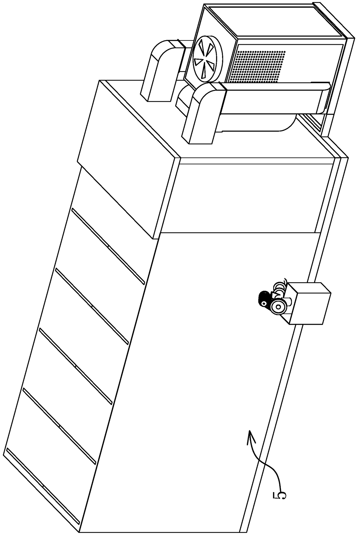
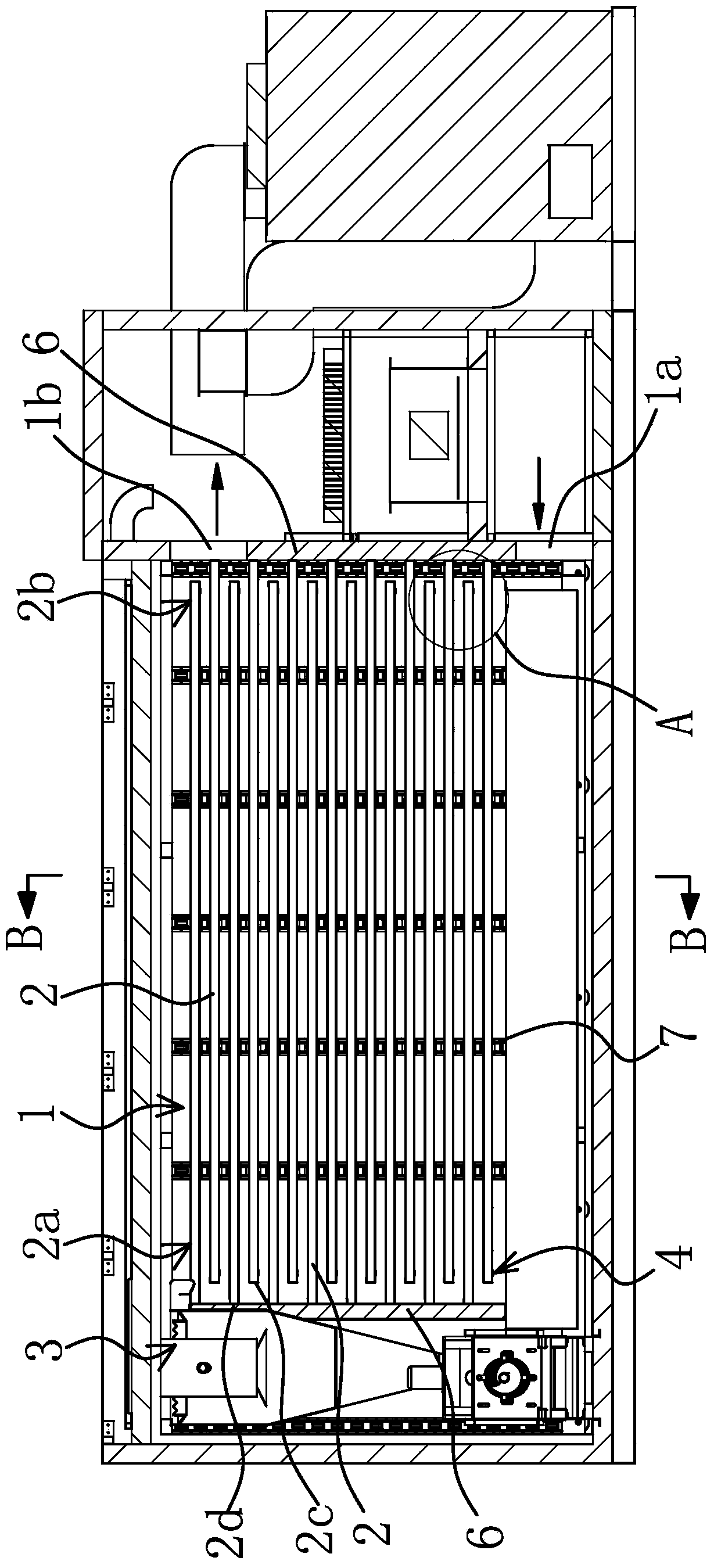
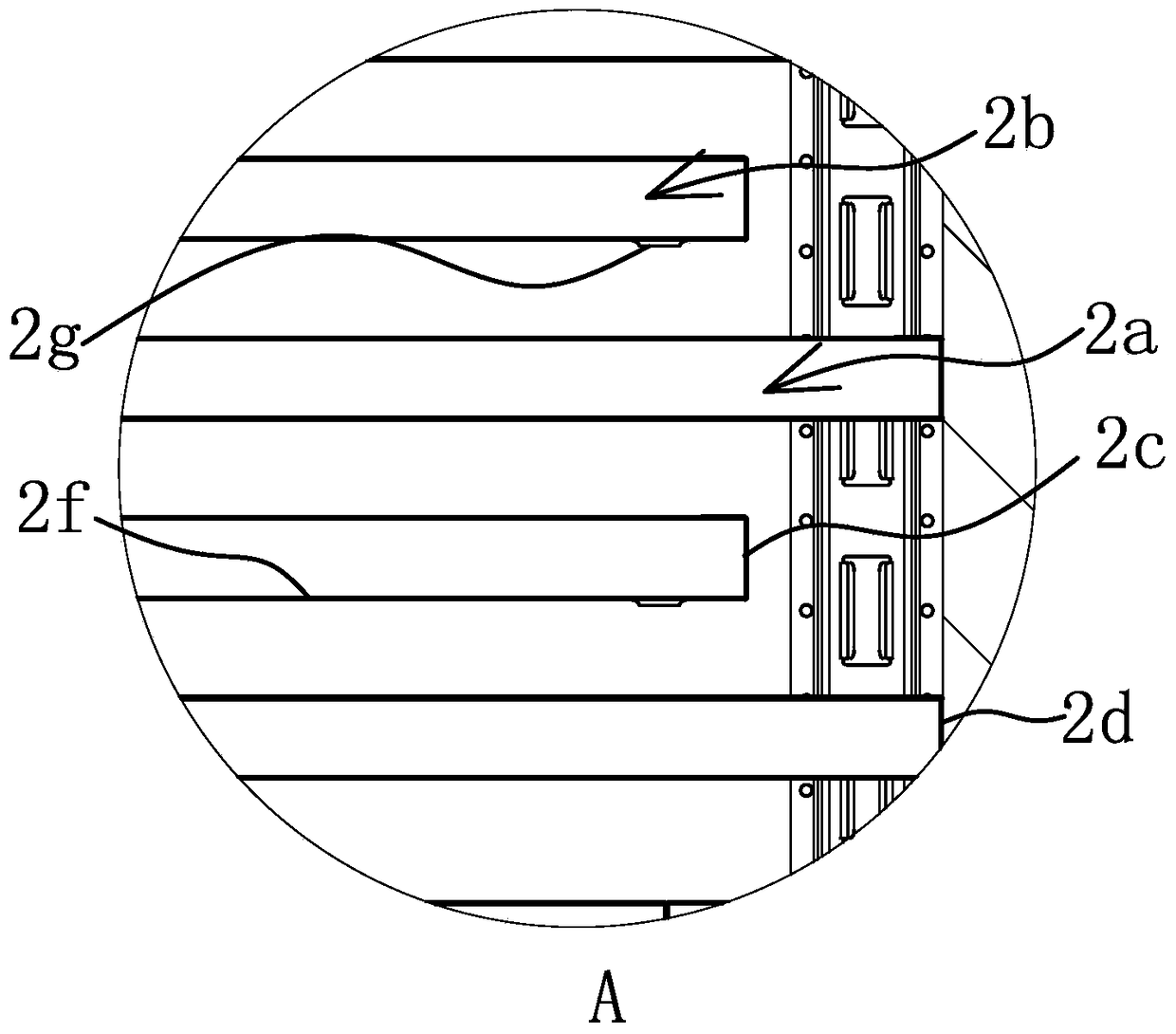
[0038] Such as Figure 1 to Figure 2 As shown, an evaporation system of wastewater treatment equipment, the wastewater treatment equipment 5 includes a closed evaporation chamber 1, the evaporation chamber 1 is provided with an air inlet 1a at the lower part and an air outlet 1b at the upper part, and several The layer is a plate-shaped diversion groove 2, of course, the number of diversion grooves 2 in each layer can be one or more, and the diversion groove 2 can guide the flow of waste water, and the present invention sets up stacked The diversion tank 2 has a large evaporation area, which effectively improves the evaporation efficiency. When the waste water enters the diversion tank 2, the hot air sent from the outside evaporates the water molecules in the waste liquid. The hot air enters from the bottom and discharges from the top, effectively utilizing the hot air from the The characteristic of flowing from low to high makes each layer of wastewater can effectively contac...

Embodiment 2

[0050] Such as Figure 12 , Figure 13 As shown, the structure and principle of this embodiment are basically the same as that of Embodiment 1, the difference is that: the water inlet structure 3 includes a sprinkler pipe 3b fixedly connected to the evaporation chamber 1, and the side wall of the evaporation chamber 1 is provided with a water sprinkling pipe. The through hole through which the pipe 3b passes, and the sprinkler pipe 3b is provided with a number of uniformly arranged sprinkler holes 3b1 on the side facing the guide tank 2 . The water supply to the evaporation chamber 1 through the water sprinkling pipe 3b is convenient and fast, and the water sprinkling hole 3b1 is directly aligned with the diversion groove 2, effectively ensuring that the water flow evenly enters the diversion groove 2 for subsequent evaporation.


PUM


Abstract

The invention provides an evaporation system of wastewater treatment equipment, and belongs to the technical field of environmental engineering. The evaporation system of the wastewater treatment equipment solves the problem that the evaporation efficiency of the evaporation system of the existing wastewater treatment equipment is low. The evaporation system of the wastewater treatment equipment of the improved structure comprises an evaporation chamber, wherein a plurality of layers of flow guide grooves are fixed in the evaporation chamber; the evaporation chamber is integrally sealed; the evaporation chamber is provided with an air inlet positioned at the lower part and an air outlet positioned at the upper part; each flow guide groove is in a flat plate shape; a water inlet structure is arranged above the flow guide groove at the uppermost layer; a water discharging opening is formed under the flow guide groove positioned at the bottommost layer; the groove surface of each flow guide groove is in upward arrangement; the water outlet end of the flow guide groove at the upper layer and the water inlet end of the adjacent flow guide groove at the lower layer are positioned at the same side; the water outlet end of each flow guide groove is provided with a first baffle plate for blocking wastewater, and is also provided with a plurality of water outlet holes through which the wastewater passes. The evaporation system of the wastewater treatment equipment of the improved structure has the advantages that the evaporation efficiency is high, and the evaporation effect is good.

Description

technical field [0001] The invention belongs to the technical field of environmental engineering, and relates to waste water treatment equipment, in particular to an evaporation system of waste water treatment equipment. Background technique [0002] In order to meet environmental protection requirements, electroplating wastewater needs to be treated. Electroplating wastewater comes from the electroplating production process, which consists of three parts: electroplating pretreatment process, electroplating process and electroplating post-treatment process. Each process produces wastewater to a certain extent. Among them, the rinsing wastewater of plating parts in the electroplating production process is one of the main sources of electroplating wastewater, so the wastewater contains a lot of electroplating sludge. However, the toxicity of electroplating wastewater is very high, which is harmful to human body, soil and animal growth. If it is directly discharged into rivers...

Claims


Application Information

Patent Timeline
Patent Type & Authority Patents(China)
IPC IPC(8): C02F1/04C02F9/10
CPCY02W10/37
Inventor 阮卜琴薛能彬吴昌文王炳昌
Owner 阮卜琴
Why Eureka
Try Eureka