Clean micro-charging technology suitable for MEMS micro thruster array chip

An array chip and micro-propeller technology, which is applied to jet propulsion devices, machines/engines, rocket engine devices, etc. High, troublesome MEMS micro-thrust array chip preparation and performance and other issues, to achieve the effect of wide material adaptability, high precision and high efficiency

Active Publication Date: 2016-05-25
NO 55 INST CHINA ELECTRONIC SCI & TECHNOLOGYGROUP CO LTD
View PDF5 Cites 0 Cited by
  • Summary
  • Abstract
  • Description
  • Claims
  • Application Information

AI Technical Summary

Problems solved by technology

[0004] The present invention proposes a clean micropowdering process suitable for MEMS microthruster array chips, and its purpose is to improve the cleanness between the micropowder chamber array layer and the microjet hole array layer during the processing of MEMS microthruster array chips. Excellent bonding efficiency and bonding performance; solve the technical problems that plague the preparation and performance of MEMS micro-thruster array chips in the prior art and affect the low bonding efficiency and bonding strength of the micro-chamber array layer and the micro-jet array layer, etc. craft problem

Method used


Image

  • Clean micro-charging technology suitable for MEMS micro thruster array chip
  • Clean micro-charging technology suitable for MEMS micro thruster array chip
  • Clean micro-charging technology suitable for MEMS micro thruster array chip

Examples


Embodiment Construction

[0019] A cleaning micro-charge process suitable for MEMS micro-thruster array chips includes the following steps:

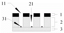
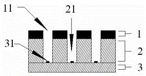
[0020] 1) According to the diameter and distribution of the micro-pharmaceutical chamber array layer 2, the corresponding separator micro-vias 11 are processed on the separator 1 with the micro-hole array, and the separator 1 with the micro-hole array is fixed on The surface of the array layer 2 of the micro-drug chamber;

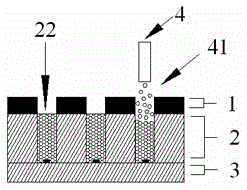
[0021] 2) Fill the propellant energetic material in the micro-medicine chamber 22 after the filling is completed;

[0022] 3) After completing the charge process of the micro-medicine chamber array layer 2, remove the partition 1 with the micro-hole array on the surface of the micro-medicine chamber array layer 2 to expose the micro-medicine chamber array layer 2 protected by the partition 1 with the micro-hole array Clean technical surface;

[0023] 4) Perform subsequent bonding steps to improve bonding power and bonding performance by ensuring that...


PUM


Abstract

The invention provides a clean micro-charging technology suitable for an MEMS micro thruster array chip. The technology includes the following steps that firstly, according to the diameter and distribution of a micro-chemical chamber array layer, corresponding partition board micro through holes are machined in partition boards of an array with micro pores, and the partition boards of the array with the micro pores are fixed to the surface of the micro-chemical chamber array layer; secondly, a micro-chemical chamber is filled with propellant energy-containing materials; thirdly, the partition boards of the array with the micro pores on the upper surface of the micro-chemical chamber array layer are removed, and a clean technological face, protected by the partition boards of the array with the micro pores, of the micro-chemical chamber array layer is exposed; fourthly, the subsequent bonding step is conducted, and the cleanliness of the surface of the micro-chemical chamber array layer is guaranteed. The method has the advantages that material adaptability is wide; the micro-porous array on the partition boards can be machined through the MEMS technology, and precision and efficiency are high; high-precision positioning marks can be conveniently machined in the partition boards, it can be guaranteed that the micro-porous array of the partition boards and a micro-chemical chamber array are concentric in the vertical direction through the alignment technology, and it is guaranteed that the micro-charging process is smoothly completed.

Description

Technical field [0001] The invention relates to the technical field of micro-thruster array chips based on MEMS technology, in particular to the technology of MEMS micro-thruster array chips that are filled with propellant and other energetic materials in a micro-drug chamber array to generate micro-thrust / micro-impulse field. Background technique [0002] At present, MEMS micro-thruster array chip technology is a powerful competitive technology that meets the needs of micro-spacecraft attitude and orbit control represented by micro-satellites and micro-satellite constellations. With the advancement of MEMS technology, the diameter of the micro-chamber of the MEMS micro-thruster array chip has entered the sub-millimeter scale, ensuring that the high-density micro-chamber array layer is clean after the micro-charge is completed. One of the key technologies for the successful bonding of the micro-jet hole array layer and the improvement of the bonding performance. So far, most of...

Claims


Application Information

Patent Timeline
Patent Type & Authority Applications(China)
IPC IPC(8): F02K9/24
CPCF02K9/24
Inventor 朱健王守旭黄旼贾世星石归雄焦宗磊
Owner NO 55 INST CHINA ELECTRONIC SCI & TECHNOLOGYGROUP CO LTD
Why Eureka
Try Eureka