
Fretting wear test device capable of conducting X-ray photoelectron spectroscopy analysis in situ

A photoelectron spectroscopy and fretting wear technology, which is applied in the direction of material analysis, measurement device, and material analysis using wave/particle radiation. The effect of reliable data support, reliable fretting service performance, and accurate evolution law

Inactive Publication Date: 2016-05-25
SOUTHWEST JIAOTONG UNIV +10
View PDF9 Cites 6 Cited by
  • Summary
  • Abstract
  • Description
  • Claims
  • Application Information

AI Technical Summary

Problems solved by technology

However, the test and transportation process of the specimens are all exposed to the atmospheric environment, and the air is easily attached to the surface of the specimens, and the wear scar surface of the specimens is polluted by air, so it is impossible to accurately measure the fretting serviceability of the specimens in a vacuum environment. Composition of wear debris and its evolution law

Method used


Image

  • Fretting wear test device capable of conducting X-ray photoelectron spectroscopy analysis in situ
  • Fretting wear test device capable of conducting X-ray photoelectron spectroscopy analysis in situ
  • Fretting wear test device capable of conducting X-ray photoelectron spectroscopy analysis in situ

Examples


Embodiment approach

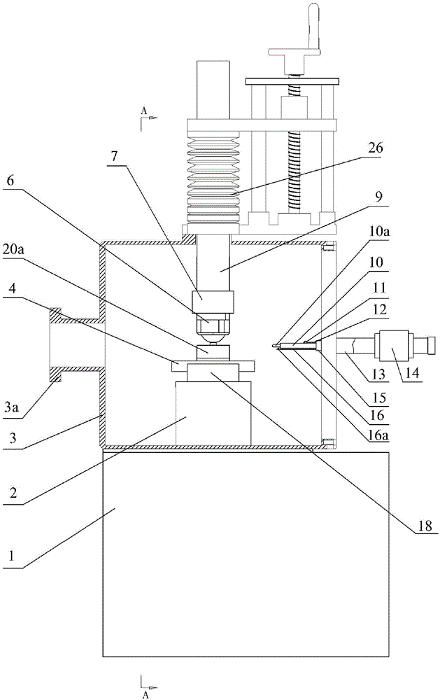
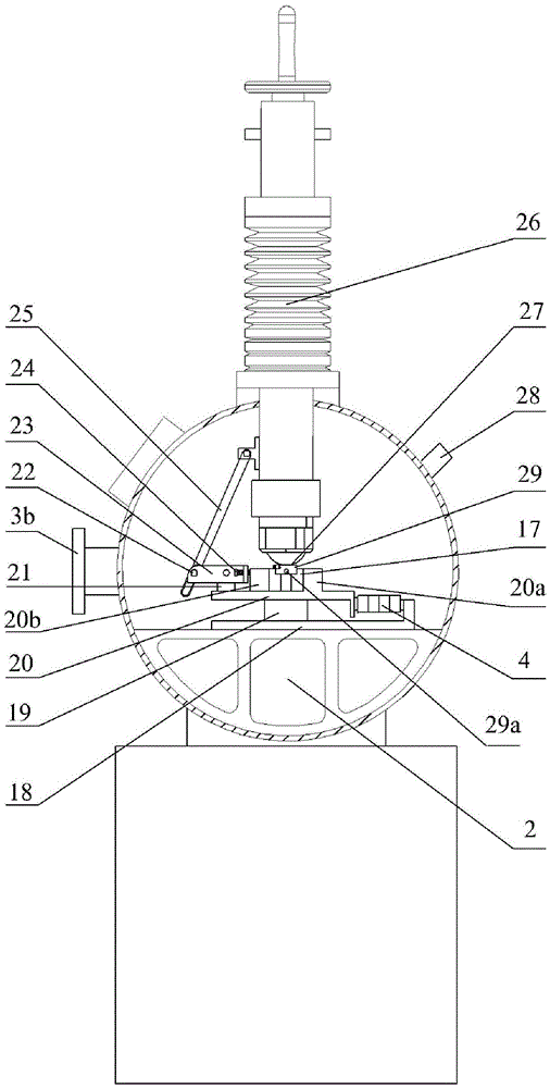
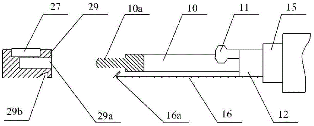
[0034] Figure 1-3 Shown, a specific embodiment of the present invention, a fretting wear test device that can perform X-ray photoelectron spectroscopy analysis in situ, including X-ray photoelectron spectroscopy analyzer, fretting wear testing machine, fretting wear tester The force applying rod 9, the three-dimensional force sensor 7, the upper clamp 6, the lower clamp 29 and the lower clamp fixing mechanism on the machine are characterized in that:

[0035]The middle and lower part of the force applying rod 9, the three-dimensional force sensor 7, the upper clamp 6, the lower clamp 29 and the fixing mechanism of the lower clamp are all sealed and wrapped in the vacuum chamber 3, and the bottom of the vacuum chamber 3 is installed on the box-shaped base 1 the top of;

[0036] Vacuum gauge 28 is installed on the described vacuum chamber 3, and the left part of vacuum chamber 3 is provided with horizontal connection pipe 3a, and connection pipe 3a is connected with the vacuum...


PUM


Abstract

The invention relates to a fretting wear test device capable of conducting X-ray photoelectron spectroscopy analysis in situ. According to the main structure of the fretting wear test device, the lower middle portion of a force applying rod of a fretting wear test machine and all components below the lower middle portion are wrapped in a vacuum cavity in a sealed mode; a vacuum gauge is installed on the vacuum cavity, the left portion of the vacuum cavity is connected with a vacuum sample introduction cavity of an X-ray photoelectron spectroscopy analysis meter through a connecting pipe, the rear portion of the vacuum cavity is connected with a vacuum pump, and the right portion of the vacuum cavity is connected with a magnetic force rod in a sealed mode; a push rod is sleeved with an inner cavity of the magnetic force rod, and the peripheral face of the magnetic force rod is sleeved with a magnetic ring with magnetism; the right portion of the push rod has magnetism, and a clamping device capable of being clamped with a lower clamp of the fretting wear test machine is installed at the left end of the push rod. After a vacuum fretting wear test is completed, the fretting wear test device can immediately conduct in-situ X-ray photoelectron spectroscopy analysis on a wear crack surface and wear debris components in the same vacuum environment, and the fretting service performance and damage mechanism of materials in the vacuum environment can be obtained more accurately and reliably.

Description

technical field [0001] The invention relates to a fretting wear test device, in particular to a vacuum fretting wear test method for measuring the tangential fretting wear performance of materials under vacuum working conditions, and especially studies the evolution law of wear debris components. technical background [0002] Fretting wear refers to the micron-scale reciprocating motion of closely bonded surfaces caused by external vibrations. The contact surface damage of mechanical parts caused by fretting or the initiation, expansion and fracture of cracks will lead to the failure of the entire operating system. The formation and oxidation of wear debris play an important role in the fretting wear process. [0003] Under different vacuum degrees, oxygen partial pressures, and inert atmosphere environments, there are differences in the formation and oxidation of wear debris between materials in contact with each other, resulting in significant changes in fretting wear per...

Claims


Application Information

Patent Timeline
IPC IPC(8): G01N3/56G01N3/04
CPCG01N3/04G01N3/56G01N23/2273
Inventor 朱旻昊彭金方万幸芝蔡振兵刘新龙林映武张晓宇莫继良章武林刘曦洋
Owner SOUTHWEST JIAOTONG UNIV
Learn More