UUV route planning method with necessary points under obstacle environment

A technology of route planning and must-pass points, applied in three-dimensional position/channel control, etc., can solve problems such as unreasonable routes, uncertain costs, and difficult to determine the pros and cons of algorithms

Active Publication Date: 2016-05-25
HARBIN ENG UNIV
View PDF11 Cites 9 Cited by
  • Summary
  • Abstract
  • Description
  • Claims
  • Application Information

AI Technical Summary

Problems solved by technology

[0003] Defects of the existing technology: due to the distribution of obstacles, the path cost between two must-pass points is uncertain, and the method of using traditional TSP planning to process intersecting line segments cannot guarantee the optimality of the path, such as figure 1 As shown, according to the traversal order of the original TSP,...

Method used


Image

  • UUV route planning method with necessary points under obstacle environment
  • UUV route planning method with necessary points under obstacle environment
  • UUV route planning method with necessary points under obstacle environment

Examples


specific Embodiment approach 1

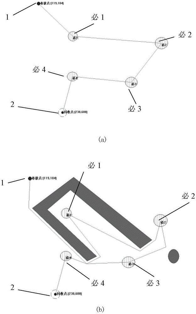
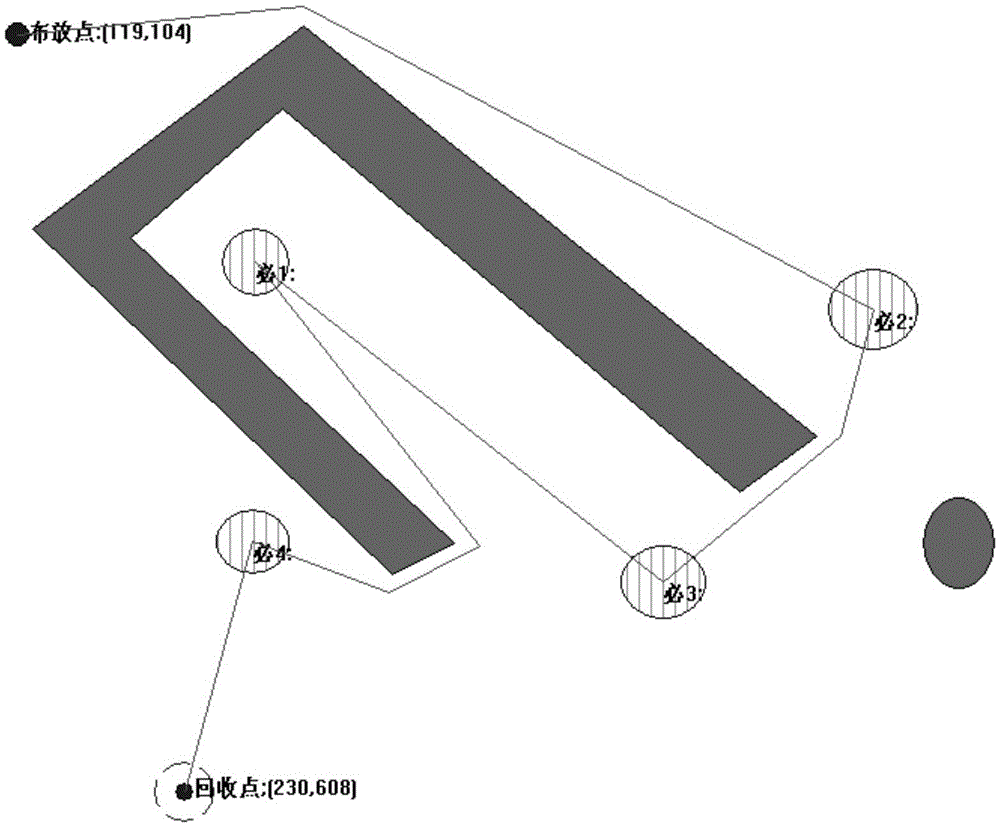
[0027] Specific implementation mode one: as Figure 1~2 As shown, a UUV route planning method with necessary points in an obstacle environment described in this embodiment, the specific process is:

[0028] The obstacle environment where the UUV is located is modeled by a geometric environment model, and the obstacles in the environment are described by closed geometric figures composed of points and lines;

[0029] The implementation process of the UUV route planning method is:

[0030] Step 1. Calculate the estimated distance between the UUV deployment point, the recovery point and all necessary points in the obstacle environment:

[0031] Step 2. With the deployment point as the starting point and the recovery point as the end point, use the TSP (traditional TSP) algorithm to plan the traversal order of all the necessary points for the UUV, so that the UUV starts from the deployment point, traverses all the necessary points, and then returns to The sum of estimated distan...

Embodiment

[0038] For the UUV route planning method with necessary points in the obstacle environment described in the above specific implementation mode, the following embodiments are given:

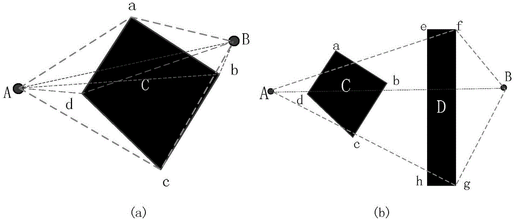
[0039] 1. Estimation method of path cost between two must-pass points

[0040] Such as figure 2 shown. Suppose you want to estimate the path cost between the two necessary points of A and B, the line segment AB intersects with the obstacle C, so the path cost of mutual transfer between A and B cannot directly use the straight-line distance. In this paper, the shortest path required for detour is taken as the transfer cost between A and B. The calculation principle and steps are as follows (with figure 2 (a) as an example):

[0041] 1 According to the coordinates of the necessary points A and B, obtain the AB straight line equation y-Mx-N=0, where Then form an area discriminant function F(x,y)=y-Mx-N that can distinguish a point on the upper side or lower side of the line

[0042] 2 Putti...


PUM


Abstract

The invention relates to a UUV route planning method with necessary points under the obstacle environment, belongs to the UUV control technology field and aims to realize the shortest path as UUV starts from a laying point, traverses all the necessary points and then returns to a recovery point. According to the method, under the obstacle environment, estimated route distances between the UUV laying point and the recovery point and between every two of the necessary points are calculated; the laying point is taken as the start point, the recovery point is taken as the terminal point, the sequence of the UUV traversing all the necessary points is planned through a TSP algorithm, the total estimated path of the UUV starting from the laying point, traversing all the necessary point and returning to the recovery point is made to be shortest; after optimization, the route can be acquired on the condition that the total estimated path of the UUV starting from the laying point, traversing all the necessary point, returning to the recovery point and can further avoid all obstacles is shortest. Path cost between two necessary points can be estimated through geometric determination, an ant colony algorithm is further utilized to plan a TSP scheme on the basis of the estimation cost, namely the necessary point traversing sequence, a variable sub goal point ant colony is further utilized to plane a route capable of realizing obstacle avoidance.

Description

technical field [0001] The invention relates to a UUV route planning method, which belongs to the technical field of UUV control. Background technique [0002] At present, there are many literatures on path planning, and most of the planning goals are to find the shortest obstacle-avoiding path from the deployment point to the recovery point that can avoid obstacles. In practical applications, the mission of UUV (unmanned underwater vehicle) may be to return to the recovery point after traversing several necessary points and completing corresponding tasks. This seems to be a TSP problem. However, the TSP problem in the obstacle environment is very different from the traditional TSP problem, because the random distribution of obstacles will cause the path cost between two points to be uncertain, which requires additional processing algorithms. At present, there are not many literatures that consider the necessary points in the obstacle environment, such as the representative...

Claims


Application Information

Patent Timeline
IPC IPC(8): G05D1/10
CPCG05D1/10
Inventor 王宏健张雪莲李庆陈涛严浙平
Owner HARBIN ENG UNIV
Why Eureka
Try Eureka