A chaotic laser emitting device for communication cable fault detection

A technology of fault detection and chaotic laser, which is applied in the direction of electromagnetic transmitters, electrical components, electromagnetic wave transmission systems, etc., can solve the problems of poor spectrum flatness and low proportion of low-frequency energy of chaotic lasers, etc., and achieve the effect of reasonable structure and ingenious design

Active Publication Date: 2017-10-10
TAIYUAN UNIV OF TECH
View PDF3 Cites 0 Cited by
  • Summary
  • Abstract
  • Description
  • Claims
  • Application Information

AI Technical Summary

Problems solved by technology

[0004] In order to solve the problems of low proportion of chaotic laser low-frequency energy and poor frequency spectrum flatness generated by existing chaotic laser generating devices, the present invention provides a chaotic laser emitting device for fault detection of communication cables

Method used


Image

  • A chaotic laser emitting device for communication cable fault detection
  • A chaotic laser emitting device for communication cable fault detection
  • A chaotic laser emitting device for communication cable fault detection

Examples


Embodiment 1

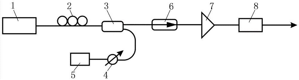
[0014] A chaotic laser emitting device for communication cable fault detection, including a semiconductor laser 1, a polarization controller 2, a 1×2 main fiber coupler 3, an optical attenuator 4, a fiber feedback mirror 5, an optical isolator 6, and an optical amplifier 7. Low-frequency enhancement device; wherein, the output end of semiconductor laser 1 is connected to the input end of polarization controller 2; the output end of polarization controller 2 is connected to the input end of 1×2 main fiber coupler 3; 1×2 main fiber Two output ends of coupler 3 are connected with the input end of optical attenuator 4 and the input end of optical isolator 6 respectively; The output end of optical attenuator 4 is connected with the input end of optical fiber feedback mirror 5; The output end of optical isolator 6 It is connected with the input end of the optical amplifier 7; the output end of the optical amplifier 7 is connected with the input end of the low frequency enhancement de...

Embodiment 2

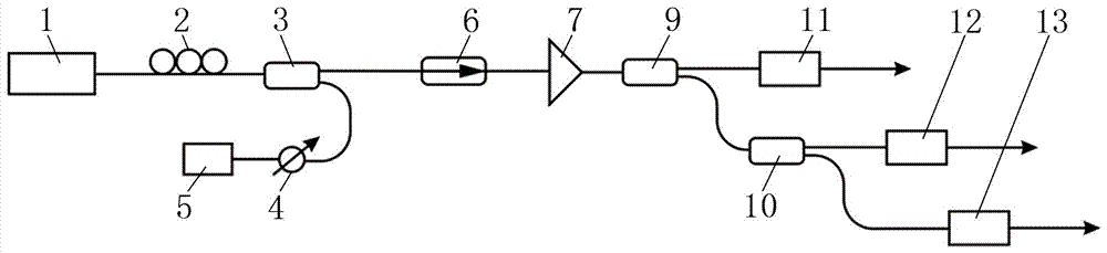
[0018] A chaotic laser emitting device for communication cable fault detection, including a semiconductor laser 1, a polarization controller 2, a 1×2 main fiber coupler 3, an optical attenuator 4, a fiber feedback mirror 5, an optical isolator 6, and an optical amplifier 7. Low-frequency enhancement device; wherein, the output end of semiconductor laser 1 is connected to the input end of polarization controller 2; the output end of polarization controller 2 is connected to the input end of 1×2 main fiber coupler 3; 1×2 main fiber Two output ends of coupler 3 are connected with the input end of optical attenuator 4 and the input end of optical isolator 6 respectively; The output end of optical attenuator 4 is connected with the input end of optical fiber feedback mirror 5; The output end of optical isolator 6 It is connected with the input end of the optical amplifier 7; the output end of the optical amplifier 7 is connected with the input end of the low frequency enhancement de...


PUM


Abstract

The invention relates to the technology of communication cable fault detection, specifically a chaotic laser transmitter for communication cable fault detection. The invention solves problems that the low-frequency energy of the chaotic laser generated by a conventional chaotic laser generation device is low in percentage, and the frequency spectrum flatness is poor. The transmitter comprises a semiconductor laser, a polarization controller, a 1*2 main fiber coupler, an optical attenuator, a fiber feedback mirror, an optical isolator, a light amplifier, and a low-frequency enhancement device. An output end of the semiconductor laser is connected with the input end of the polarization controller. The output end of the polarization controller is connected with the input end of the 1*2 main fiber coupler. The two output ends of the 1*2 main fiber coupler are respectively connected with the input end of the optical attenuator and the input end of the optical isolator. The output end of the optical attenuator is connected with the input end of the fiber feedback mirror. The transmitter is suitable for the detection of a communication cable fault.

Description

technical field [0001] The invention relates to a chaotic laser generation technology in communication cable fault detection, in particular to a chaotic laser emitting device for communication cable fault detection. Background technique [0002] In recent years, as the transmission medium of control signals and communication signals, communication cables have been widely used in aircraft, ships, motor vehicles, spaceships and other equipment. In the actual application process, communication cables will fail due to the special working environment and aging lines. The light ones will cause electrical equipment to stop working, and the severe ones will cause accidents in aircraft, ships, trains, and spaceships. Therefore, accurate detection of communication cable faults is very important. At present, the detection of communication cable faults is mainly realized by reflectometry, and the generation of chaotic laser is the primary link to realize high-precision and long-distanc...

Claims


Application Information

Patent Timeline
Patent Type & Authority Patents(China)
IPC IPC(8): H04B10/50H04B10/077
CPCH04B10/0771H04B10/503
Inventor 韩红王大铭王安帮王冰洁徐航赵彤王龙生
Owner TAIYUAN UNIV OF TECH
Why Eureka
Try Eureka