Information display method and video monitoring platform

A technology for video surveillance and information display, applied in the direction of digital output to display equipment, TV, image communication, etc., can solve the problems of multi-camera split-screen display, video surveillance, affecting the speed of video surveillance to view emergency information, etc. Improve the efficiency of troubleshooting, rapid positioning and processing

Inactive Publication Date: 2016-05-25
GUANGDONG VIMICRO
View PDF9 Cites 22 Cited by
  • Summary
  • Abstract
  • Description
  • Claims
  • Application Information

AI Technical Summary

Problems solved by technology

[0008] The technical problem to be solved by the present invention is that when there are multiple cameras in a certain incident area, the prior art all selects a single camera on the GIS map for video playback or selects videos one by one for display, thereby affecting the ability to view emergency

Method used


Image

  • Information display method and video monitoring platform
  • Information display method and video monitoring platform
  • Information display method and video monitoring platform

Examples


Embodiment 1

[0035] Embodiment 1 of the present invention provides a method for information display, the steps are as follows:

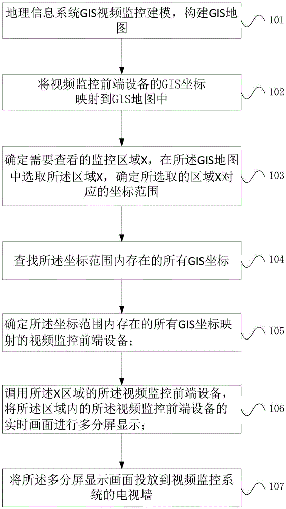
[0036] Step 101, it is necessary to complete the modeling of geographic information system GIS video surveillance, and construct a GIS map;

[0037] In step 102, the video monitoring equipment in the video monitoring network system, such as a camera, is mapped to the GIS map, and the specific steps are as follows:

[0038] Obtain GIS coordinates corresponding to each camera in the video surveillance system, where the GIS coordinates include longitude and latitude. Mapping the GIS coordinates into a corresponding GIS map;

[0039] Step 103, determine the area X that needs to be monitored and displayed, and select the area X in the GIS map; determine the coordinate range corresponding to the selected area X;

[0040] Step 104, searching for GIS coordinates existing within the coordinate range;

[0041] Step 105, determining the camera mapped to the GIS coordinat...

Embodiment 2

[0045] Embodiment 2 of the present invention provides another method for viewing real-time video from multiple cameras by region, the steps are as follows:

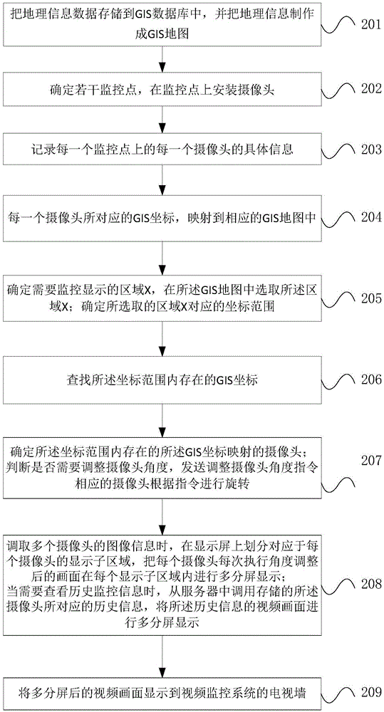
[0046] Step 201, according to the spatial data engine in the jurisdiction under the jurisdiction of the monitoring platform, the geographic information data is stored in the GIS database, and the geographic information is made into a GIS map;

[0047] Step 202, determine a number of monitoring points in the jurisdiction area under the jurisdiction, and install cameras on the monitoring points;

[0048] Step 203, recording the specific information of each camera on each monitoring point, such as the corresponding GIS coordinates of the camera, camera GUID, camera type, camera angle, etc.;

[0049] Step 204, according to the GIS coordinates corresponding to each camera in the video surveillance system, the GIS coordinates include longitude and latitude. Mapping the GIS coordinates into a corresponding GIS map;

[0050] St...

Embodiment 3

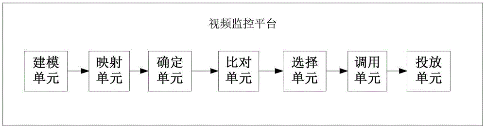
[0057] A video monitoring platform, comprising: a modeling unit, a mapping unit, a determining unit, a comparing unit, a selecting unit, a calling unit and a projecting unit connected in sequence.

[0058] The modeling unit completes the modeling of GIS video surveillance and constructs GIS maps;

[0059] The mapping unit acquires GIS coordinates corresponding to each camera in the video surveillance system, where the GIS coordinates include longitude and latitude. Mapping the GIS coordinates corresponding to each camera to the corresponding GIS map constructed by the modeling unit;

[0060] The determination unit determines the area X that needs to be monitored and displayed, and selects the area X in the GIS map; determines the coordinate range corresponding to the selected area X;

[0061] Comparing the units to find the GIS coordinates existing in the coordinate range;

[0062] The selection unit, according to the GIS coordinates found by the comparison unit, determines ...


PUM


Abstract

The invention relates to the technical field of video monitoring, and provides an information display method and a video monitoring platform. The video monitoring platform comprises a mapping unit, a determination unit, a comparison unit, a selection unit and a calling unit, wherein the mapping unit is used for mapping the GIS coordinates of video monitoring front-end devices into a GIS map; the determination unit is used for determining a monitoring area needing to be checked; the comparison unit is used for finding all GIS coordinates existing in a coordinate range; the selection unit is used for determining the video monitoring front-end devices mapped by the all GIS coordinates existing in the coordinate range; and the calling unit is used for calling the video monitoring front-end devices of an X area. According to the information display method, through defining an area on the GIS map, selecting all cameras in the area according to the area coordinate, and displaying corresponding camera videos in multiple screens or selecting to project the same to a large-screen video wall for displaying, the plurality of camera videos of an incident site can be viewed rapidly in case of emergency, and thereby rapid positioning and processing of the emergency are achieved.

Description

technical field [0001] The invention relates to the technical field of video monitoring, in particular to an information display method and a video monitoring platform. Background technique [0002] In 2009, the Public Security Bureau clearly proposed to comprehensively promote the construction of the urban monitoring and alarm network system, and the construction of more than 90% of the large and medium-sized cities in the country covers the urban monitoring of entrances and exits, main roads, public complex places, places prone to incidents, key units, and communities The alarm network system platform comprehensively applies the interconnection of various alarm and monitoring systems to provide services for preventing and combating illegal and criminal activities. [0003] In order to cope with the new situation of public security prevention and strengthen and innovate social management methods, public security organs at all levels have carried out the construction of a so...

Claims


Application Information

Patent Timeline
IPC IPC(8): H04N7/18G06F3/14
CPCH04N7/181G06F3/1446
Inventor 纪宏达韩峻
Owner GUANGDONG VIMICRO
Why Eureka
Try Eureka