LED drive circuit based on constant-ON-time control

A constant on-time, LED-driven technology, applied in energy-saving control technology, lamp circuit layout, electric light source, etc., can solve the problems of switching frequency change, complex structure, large ripple, etc., to achieve fast response, small current ripple, large The effect of market value

Inactive Publication Date: 2016-05-25
WUHU RUIXIN ELECTRONICS TECH CO LTD
View PDF2 Cites 0 Cited by
  • Summary
  • Abstract
  • Description
  • Claims
  • Application Information

AI Technical Summary

Problems solved by technology

[0003] The technical problem to be solved by the present invention is to provide an LED drive circuit based on constant on-time control, which can be widely used in different occasions such as general LED lighting, high-power LED street lighting, solar LED landscape lighting or automobile lighting, etc. It is a very practical and high-power LED lighting drive circuit with great market value. It solves the problem that the switching frequency of ordinary LED circuits changes with the input voltage, while the ripple is large and the structure is complicated.

Method used


Image

  • LED drive circuit based on constant-ON-time control

Examples


specific Embodiment approach

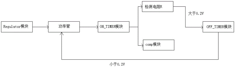
[0013] A specific embodiment of the present invention: an LED drive circuit based on constant on-time control, wherein the LED drive circuit includes a Regulator module, an ON_TIMER module, an OFF_TIMER module, a COMP module detection resistor R, and a power tube. When the system is powered on In an instant, the current passes through the Regulator module, so that it generates power inside and supplies power to each module, so that the drive circuit system starts to work; first, the power tube is turned on, and the turn-on time is set by the ON_TIMER module. At this time, the circuit flows through The current in the LED gradually increases. When the timing time is up, the power tube is turned off, and the off time is set by the OFF_TIMER. At this time, the current in the LED gradually decreases; when the timing time is up, the COMP module detects the If the voltage on the resistor R is higher than 0.2V, it will continue to be closed, and if the voltage is lower than 0.2V, the p...


PUM


Abstract

The invention discloses an LED drive circuit based on constant-ON-time control. The LED drive circuit is characterized by comprising a Regulator module, an ON_TIMER module, an OFF_TIMER module, a COMP module, a detection resistor R and a power tube. The LED drive circuit can be widely applied to occasions including general LED illumination, large power LED street lamp illumination, solar LED landscape lamps and car light illumination, is a large power LED illumination drive circuit with high market values, and solves the problems that the switching frequency changes with the input voltage, the ripples are high and the structure is complex in a common LED circuit.

Description

technical field [0001] The invention relates to LED circuits, in particular to an LED driving circuit based on constant on-time control. Background technique [0002] In the case of a prosperous market, the quality of LED products and the performance of driving circuits are also uneven. In terms of improving the performance of the LED drive circuit alone, we should focus on overcoming the following problems: first, long life, how to improve the life of the electrolytic capacitor at high temperature to improve the life of the entire LED drive circuit; second, high efficiency, LED drive The low conversion efficiency of the circuit will directly contradict the energy-saving characteristics of LED lighting; the third is the constant current accuracy, high constant current accuracy is conducive to the stability of LED light emission, and is conducive to the large-scale application of LED in landscape lighting. Finally, the driving power supply for high-power LED street lighting ...

Claims


Application Information

Patent Timeline
Patent Type & Authority Applications(China)
IPC IPC(8): H05B37/02
CPCY02B20/40
Inventor 朱成华崔俊国
Owner WUHU RUIXIN ELECTRONICS TECH CO LTD
Why Eureka
Try Eureka