A floor sweeper with infrared camera function

An infrared camera and sweeper technology, which is used in manual sweeping machinery, carpet cleaning, floor cleaning, etc., can solve the problems of the camera angle cannot be adjusted, the camera viewing angle is narrow, and the adjustment angle is small, so as to improve the bad experience and solve the problem of camera The effect of narrow viewing angle

Active Publication Date: 2017-12-22
HANGZHOU SINODOD ELECTRIC
View PDF8 Cites 0 Cited by
  • Summary
  • Abstract
  • Description
  • Claims
  • Application Information

AI Technical Summary

Problems solved by technology

[0006] The object of the present invention is to provide a floor sweeper with infrared camera function, which can improve the camera sweeper so that it has a stronger night vision function, solve the shortage of monitoring applications of ordinary camera sweepers, and can clearly view both day and night. Monitoring the home; it can also solve the problems of the camera sweeper with a narrow camera angle, the camera angle cannot be adjusted or the adjustment angle is small, etc., combined with the remote control of the Internet of Things, it can meet the needs of users to check the home situation in real time

Method used


Image

  • A floor sweeper with infrared camera function
  • A floor sweeper with infrared camera function
  • A floor sweeper with infrared camera function

Examples


Embodiment 1

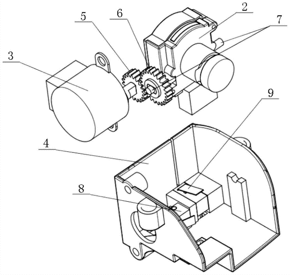
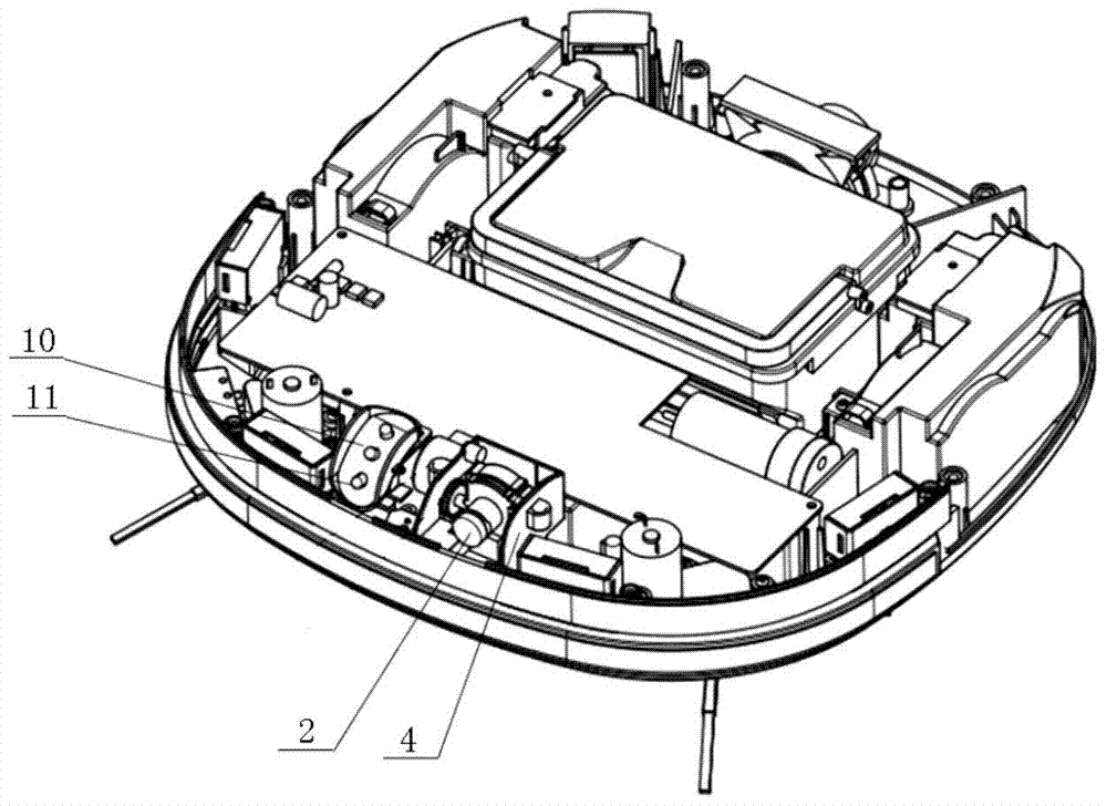
[0031] Embodiment one, such as Figure 5 As shown, the infrared lamp mounting seat 10 is ring-shaped, and is arranged in the circumferential direction of the camera 2, and several infrared lamps 11 on the infrared lamp mounting seat 10 are evenly distributed in a ring shape. In this embodiment, three infrared lamps 11 as an example.

Embodiment 2

[0032] Embodiment two, such as Figure 6 As shown, the infrared lamp mounting seat 10 is ring-shaped, and is arranged in the circumferential direction of the camera 2, and several infrared lamps 11 on the infrared lamp mounting seat 10 are vertically distributed. In this embodiment, two infrared lamps 11 are taken as an example. .

Embodiment 3

[0033] Embodiment three, such as Figure 7As shown, the infrared lamp mounting seat 10 is ring-shaped, and is arranged in the circumferential direction of the camera 2, and several infrared lamps 11 of the infrared lamp mounting seat 10 are distributed horizontally. In this embodiment, two infrared lamps 11 are taken as an example. .

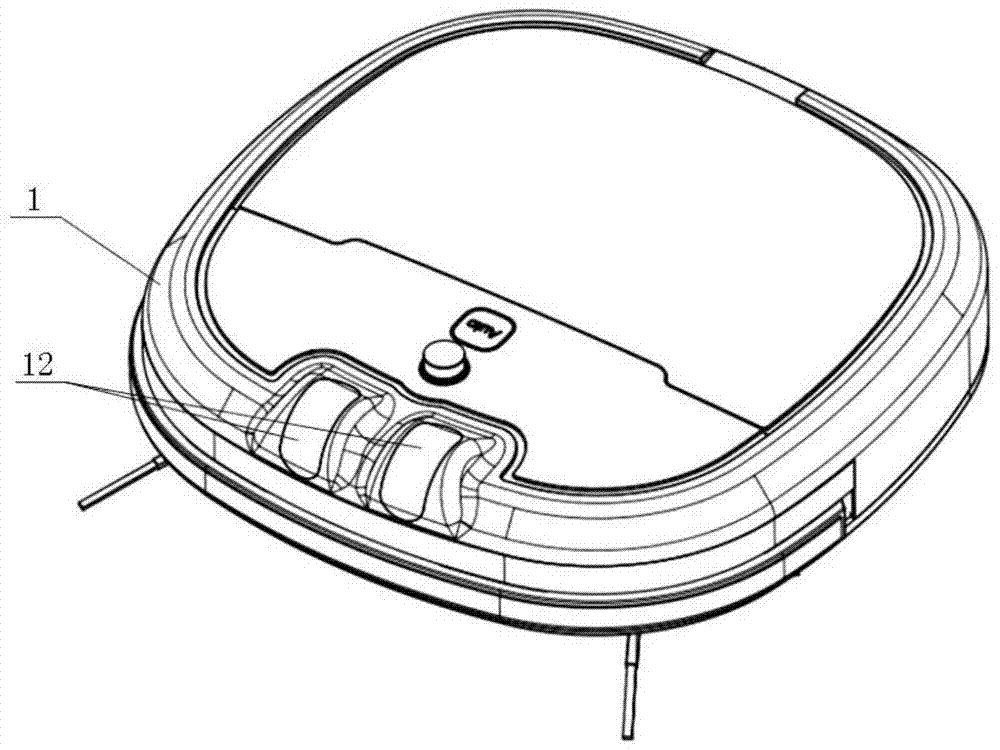
[0034] Another example, such as Figure 8 As shown, the lens of the camera 2 is provided with an infrared filter, and the housing 1 is provided with a camera single window 15, and the camera single window 15 corresponds to the camera 2 and the infrared lamp 11, and the camera single window 15 is the same It has the characteristics of one-way light transmission.

[0035] In summary, the structure of the present invention can be seen that the present invention has the following technical effects:

[0036] 1. The present invention uses infrared light as a supplementary light source for camera shooting. Because infrared light is non-visible light...


PUM


Abstract

A sweeping machine with an infrared camera function, the housing is provided with a camera, a power mechanism and a limit mechanism, the camera is connected to the power mechanism through a transmission mechanism, and an infrared supplementary light mechanism is also provided in the housing. A dust cover is also fixed, and the camera and the infrared supplementary light mechanism are arranged in the dust cover. Compared with the prior art, the infrared lamp of the present invention is used as a supplementary light source for photography and photography. Because infrared light belongs to non-visible light, it avoids The ordinary camera sweeper uses visible light as a supplementary light source, which improves the bad experience of the sweeper sweeping the floor with a flashlight. At the same time, it solves the problems of narrow camera angle, unadjustable camera angle or small adjustment angle of the camera sweeper. Combined with the Internet of Things The remote control can better meet the needs of users to check the situation at home.

Description

technical field [0001] The invention relates to the technical field of smart home equipment, in particular to a floor sweeper with an infrared camera function. Background technique [0002] With the improvement of people's living standards and the development of science and technology, sweepers are increasingly recognized by consumers because of their intelligent cleaning effectiveness. In order to meet the diversity of market demands, camera sweepers have emerged as the times require, but sweepers with camera functions on the market have the following limitations: [0003] First: There is no better solution for taking pictures in low light or night without lights. When the light is weak or there is no light at night, the camera sweeper cannot take pictures. Although some products use LED lighting to supplement light, they can realize night vision shooting, but the LED light is required to be strong and the light distribution is relatively uniform, otherwise the shooting ef...

Claims


Application Information

Patent Timeline
Patent Type & Authority Patents(China)
IPC IPC(8): A47L11/24A47L11/40H04N5/235
CPCA47L11/24A47L11/4011H04N23/74
Inventor 高新忠甘嵩凡海洋王超金彪唐翔
Owner HANGZHOU SINODOD ELECTRIC
Why Eureka
Try Eureka