
Small-sized hardware part image sorting machine

A technology of hardware parts and sorting machines, applied in sorting and other directions, can solve the problems of low positioning accuracy, affecting the detection effect, and poor overall effect, and achieve the effects of high positioning accuracy, guaranteed pass rate, and easy maintenance

Active Publication Date: 2016-06-01
NINGBO HUIHUA MASCH CO LTD
View PDF17 Cites 11 Cited by
  • Summary
  • Abstract
  • Description
  • Claims
  • Application Information

AI Technical Summary

Problems solved by technology

[0008] The purpose of the present invention is to solve the problems of high cost, complex structure, inconvenient maintenance, high failure rate, low positioning accuracy of the product on the detection platform, poor overall effect and affecting the detection effect of the existing micro-small hardware parts detection, To provide a small hardware parts image sorting machine with low cost, simple structure, easy maintenance, low failure rate, high positioning accuracy of products on the testing platform, good overall effect, and guaranteed testing quality

Method used


Image

  • Small-sized hardware part image sorting machine
  • Small-sized hardware part image sorting machine
  • Small-sized hardware part image sorting machine

Examples


Embodiment 1

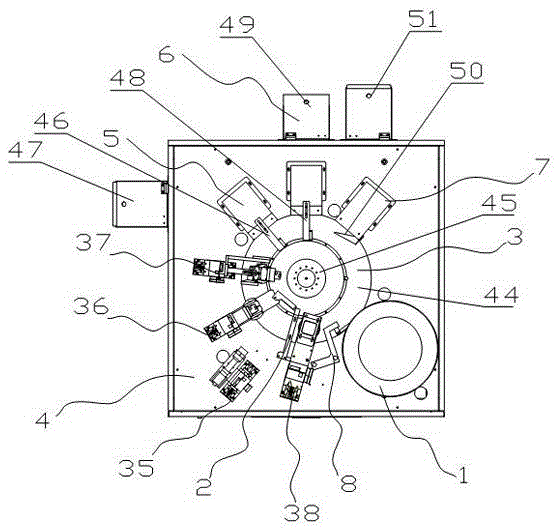
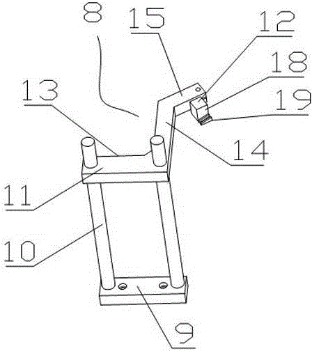
[0034] exist figure 1 , figure 2 In the shown embodiment, the image sorting machine for small hardware parts includes a vibration plate 1, a product positioning mechanism 2, a rotation detection mechanism 3, an image detection device 4, a qualified product separation mechanism 5, a defective product separation mechanism 6, and a suspected part separation mechanism. Mechanism 7 and control system, the vibrating plate 1 is connected with the rotation detection mechanism 3, the product positioning mechanism 2 is set on the station near the product entrance of the vibrating plate 1 and above the rotation detection mechanism 3, the qualified product separation mechanism 5, the defective product The separation mechanism 6 and the suspect part separation mechanism 7 are sequentially arranged on the station on the rear side of the product positioning mechanism 2 along the rotation direction of the rotation detection mechanism 3, and the image detection device 4 is arranged on the pro...

Embodiment 2

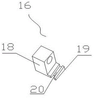
[0042] exist Figure 7 , Figure 8 , Figure 9 In the shown embodiment, the image sorting machine for small hardware parts is basically the same as Embodiment 1, the difference is that the micro-track 12 is a semi-closed micro-track 17, and the semi-closed micro-track 17 includes a track seat 18 and a wedge-shaped Track 19, the central position of wedge-shaped track 19 is provided with T-shaped track slot 21 along the length direction of wedge-shaped track ( Figure 10 ); the length of the wedge track 19 is less than 30 times the diameter of the part to be detected.

[0043] The inspection machine described in the above-mentioned embodiments guides the workpieces to be inspected from the vibrating disk to the rotating disk smoothly through a fixed dialing wheel or a guiding mechanism composed of a non-powered miniature guide rail mechanism, and evenly Spread it on the transparent turntable to realize the photographic detection and separation of workpieces, and achieve the p...


PUM


Abstract

The invention discloses a small-sized hardware part image sorting machine which comprises a vibrating disk, a product positioning mechanism, a rotary detection mechanism, an image detection device, a qualified product separation mechanism, a defective product separation mechanism, a suspected part separation mechanism and a control system. The vibrating disk is connected with the rotary detection mechanism. The product positioning mechanism is arranged on a station near a product inlet of the vibrating disk and is arranged on the rotary detection mechanism. The qualified product separation mechanism, the defective product separation mechanism and the suspected part separation mechanism are sequentially arranged on stations on the rear side of the product positioning mechanism in the rotating direction of the rotary detection mechanism. The image detection device is arranged on a station between the product positioning mechanism and the qualified product separation mechanism in the rotating direction of the rotary detection mechanism. A guiding mechanism, which is in butt joint with a product outlet, is arranged at the product inlet of the vibrating disk. A positioning correcting mechanism is arranged on a station close to the guiding mechanism. The small-sized hardware part image sorting machine is low in cost, simple in structure, convenient to maintain, low in failure rate, high in positioning precision of a product on a detection platform, and good in overall effect.

Description

technical field [0001] The invention relates to the technical field of detection machinery for small hardware parts, in particular to an image sorting machine for small hardware parts. Background technique [0002] At present, the rapid detection of small hardware parts such as small gaskets, bolts and nuts has been widely used in the realization, and in the process of rapid detection, because the vibrating plate is in a vibrating state, when the parts to be detected enter the detection turntable , it usually needs to be connected with a linear transmission mechanism. The linear transmission mechanism is usually realized by a power runner, a belt, a steel belt, etc. During the transmission process of the linear transmission mechanism, it is difficult to achieve accurate positioning of the parts to be tested, and there are generally high costs, The structure is complex, maintenance is inconvenient, the failure rate is high, the positioning accuracy of the product on the testi...

Claims


Application Information

Patent Timeline
Patent Type & Authority Applications(China)
IPC IPC(8): B07C5/34
Inventor 彭力明
Owner NINGBO HUIHUA MASCH CO LTD
Learn More