Photographing and positioning type metal plate punching device

A technology of camera positioning and punching device, which is applied in the field of sheet metal processing, can solve the problems of inaccurate sheet positioning, lack of support devices, and affecting processing quality, and achieve the effects of simple operation, simple structure, and low cost

Inactive Publication Date: 2016-06-01
无锡市通协物资有限公司
6 Cites 0 Cited by

AI-Extracted Technical Summary

Problems solved by technology

The above-mentioned punching devices or punching machines are generally operated manually, that is, the plate is adjusted by manually adjusting the clamping device to adjust the processing positi...

Method used

The present invention adjusts the processing position of workpiece by photographing positioning device and clamping block, and its structure is simple, cost is low; Adopt image contrast processing to display adjustment inf...

Abstract

The invention relates to a photographing and positioning type metal plate punching device. the photographing and positioning type metal plate punching device comprises a punching drive device, an upper template, a punching head, a clamping device and a support seat, wherein the clamping device and the support seat are arranged below the punching head; the clamping device comprises symmetrically arranged clamping blocks, and a workpiece is clamped between the clamping blocks; a photographing and positioning device is arranged between the upper template and the workpiece; indicator lights and a display screen are mounted on the front side surface of the upper template; the indicator lights, the display screen and the photographing and positioning device are connected with a control unit respectively. According to the photographing and positioning type metal plate punching device, a processed position of the workpiece is adjusted through the photographing and positioning device and the clamping blocks, and the device is simple in structure and low in cost; adjusting information is displayed in real time with adoption of image comparison processing, and the operation is simple and convenient; overall deformation of the workpiece can be prevented by the aid of the support seat, and punching blanking is facilitated by the aid of a punching groove.

Application Domain

Metal-working feeding devicesPositioning devices +1

Technology Topic

Type metalBiomedical engineering +2

Image

  • Photographing and positioning type metal plate punching device
  • Photographing and positioning type metal plate punching device

Examples

  • Experimental program(1)

Example Embodiment

[0011] The specific embodiments of the present invention will be described below in conjunction with the drawings.
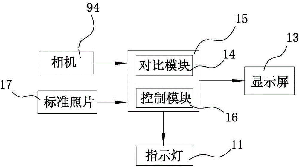
[0012] see figure 1 and figure 2 The present invention includes a punching drive device 1, an upper template 2 and a punching head 3. It also includes a clamping device and a support seat 7 located below the punching head 3. The clamping device includes a symmetrically arranged clamping block 6 that clamps The holding block 6 is of an L-shaped structure, with a detection mark 8 on its upper end surface, and the workpiece 10 is clamped between the opposed clamping blocks 6; the clamping block 6 is mounted on the first bracket 12 by means of a screw shaft 4, the screw shaft The outer end of 4 is connected to the handle 5; the support seat 7 is placed below the position of the processing hole of the workpiece 10, and the support seat 7 has a through punching groove 71 for punching and blanking; the upper template 2 and the A photographing positioning device 9 is provided between the workpieces 10, and the photographing positioning device 9 includes a camera 94 installed at the end of the rotating rod 93, and the camera 94 is used to photograph the distance between the detection marks 8 on the upper end of the opposite clamping block 6; The rod 93 is rotatably connected to the second bracket 92, the end of the rotating rod 93 is provided with a handle 91; the front side of the upper template 2 is equipped with an indicator light 11 and a display screen 13, an indicator light 11, a display screen 13 and a camera 94 Connected to the control unit 15 respectively. The control unit 15 includes a comparison module 14 and a control module 16. The comparison module 14 compares the photo of the camera 94 with the standard photo 17, and the control module 16 transmits the adjustment information to the display screen 13 according to the comparison result; The indicator 11 includes a red light and a green light: when the comparison result is that the two photos are the same, the green light of the indicator 11 is on, otherwise the red light is on.
[0013] When the workpiece 10 is installed in the present invention, the camera 94 first takes a standard photo 17, that is, the position of the detection mark 8 on the opposite clamping block 6 in the standard state; the workpiece 10 is placed between the opposite clamping blocks 6 ; Rotate the hand grip 91 to place the camera 94 at the end of the rotating rod 93 directly below the punching head 3; turn the handle 5 to adjust the clamping block 6 to initially adjust the processing position of the workpiece 10, start the camera 94 to take pictures The camera 94 compares the photo taken with the standard photo 17 through the comparison module 14 of the control unit 15. The control module 16 sends the comparison result to the display screen 13 to prompt the operator to further adjust the processing position of the processed part 10; When there is no difference between the two, the control module 16 activates the green light of the indicator 11 to complete the positioning of the workpiece 10; rotate the handle 91 to rotate the camera 94 around the second bracket 92 by 180 degrees, leaving a punching space for the punching head 3.
[0014] In the present invention, the control unit 15, the comparison module 14, the control module 16, and the indicator light 11 are all existing technologies.
[0015] The invention adjusts the processing position of the workpiece through the photographing positioning device and the clamping block, and has a simple structure and low cost; adopts image contrast processing to display adjustment information in real time, and is easy to operate; and the setting of a support block can prevent the entire workpiece from being processed It is deformed, and the set punching groove is convenient for punching and blanking.
[0016] The above description is an explanation of the invention, not a limitation of the invention. For the scope of the invention, please refer to the claims. The invention can be modified in any form without departing from the spirit of the invention.

PUM

no PUM

Description & Claims & Application Information

We can also present the details of the Description, Claims and Application information to help users get a comprehensive understanding of the technical details of the patent, such as background art, summary of invention, brief description of drawings, description of embodiments, and other original content. On the other hand, users can also determine the specific scope of protection of the technology through the list of claims; as well as understand the changes in the life cycle of the technology with the presentation of the patent timeline. Login to view more.

Similar technology patents

Body condition measuring device

InactiveUS20050234351A1simple structure
Owner:DENSO CORP

Magnetic cooling apparatus and control method thereof

ActiveUS20130180263A1simple structure
Owner:SAMSUNG ELECTRONICS CO LTD

Dual-Drivetrain of Power-Assist Vehicle

InactiveUS20100181130A1enhance uphill momentumsimple structure
Owner:CHOU WEN CHENG

Classification and recommendation of technical efficacy words

  • Simple structure
  • low cost

Sharing system for air-conditioning coat

InactiveCN107440179ASimple structureeasy to wear
Owner:QINGDAO HAIER AIR CONDITIONER GENERAL CORP LTD

Feeding device of sorter of batteries plate

InactiveCN101357717ASimple structurecooperate well
Owner:NANJING NORMAL UNIVERSITY

Emergency parachuting device and method for multiple-rotor unmanned aerial vehicle

InactiveCN103895870Aavoid aircraft crashSimple structure
Owner:SOUTH CHINA AGRI UNIV +1

System and method for transmitting wireless digital service signals via power transmission lines

ActiveUS7929940B1reduce bandwidth requirementlow cost
Owner:NEXTEL COMMUNICATIONS

System and method for determination of position

InactiveUS20090149202A1low costreduce requirement
Owner:STEELE CHRISTIAN

Adaptive antenna optimization network

InactiveUS6961368B2low costminimal space
Owner:ERICSSON INC

Antenna device and method for attaching the same

ActiveUS20150138022A1low costimproved strength characteristic
Owner:NEC CORP
Why Eureka
Try Eureka