Supercharge Your Innovation With Domain-Expert AI Agents!

Positioning method of center frame of machining cutting machine tool

A technology of cutting machine tool and positioning method, which is applied in the direction of metal processing machinery parts, metal processing equipment, manufacturing tools, etc., can solve the problems of locking, elliptical force on the end face of the workpiece, and difficult force, so as to reduce the possibility of contact and reduce the damage effect

Inactive Publication Date: 2016-06-01
邱晓霞
View PDF0 Cites 0 Cited by
  • Summary
  • Abstract
  • Description
  • Claims
  • Application Information

AI Technical Summary

Problems solved by technology

[0003] The purpose of the present invention is to overcome the problem that the force of the top column of the center frame is difficult to adjust when clamping the workpiece, and the workpiece is easily loosened to form an ellipse on the end face of the workpiece or locked due to excessive force, and to provide a machining and cutting machine tool center. rack positioning method

Method used


Image

  • Positioning method of center frame of machining cutting machine tool

Examples


Embodiment

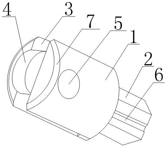
[0018] Such as figure 1 As shown, a method for positioning the center frame of a machining and cutting machine tool in the present invention includes a top cylinder 1, the top cylinder 1 is cylindrical in shape, and a hexagonal columnar socket 2 is connected to one end surface of the top cylinder 1. A guide groove 6 parallel to the axis of the top cylinder 1 is provided on the piece 2, and a mounting groove 3 is provided on the other end surface of the top cylinder 1, and the end surface is provided with an inverted platform 7, and the inverted platform surrounds the circle where the end surface is located, and the installation groove 3 The two sides on the top tube 1 are parallel to each other and symmetrical about the axis of the top tube 1, and a bearing 5 is installed in the installation groove 3, and the two ends of the bearing 5 are connected to the two sides of the top tube 1 installation groove 3, and A roller 4 is set on the bearing 5, and the radius of the roller 4 i...


PUM


Abstract

The invention discloses a positioning method of a center frame of a machining cutting machine tool. The positioning method involves a top barrel (1) which is in a cylinder shape overall, a sleeving part (2) is connected with one end face of the top barrel (1), and the other end face of the top barrel (1) is provided with an installation groove (3). The two side faces, on the top barrel (1), of the installation groove (3) are parallel and symmetric about the axis of the top barrel (1). A bearing (5) is installed in the installation groove (3). The two ends of the bearing (5) are connected with the two side faces of the installation groove (3) of the top barrel (1). The bearing (5) is sleeved with a roller (4), and the radius of the roller (4) is larger than the distance between the axis of the bearing (5) and the end face, where the installation groove (3) is located, of the top barrel (1). The top barrel is provided with the installation groove, the bearing is installed in the installation groove, and the bearing is sleeved with the roller, so that friction force between a top wheel and a workpiece is converted into rolling friction force, the situation that the workpiece is locked is reduced, and workpiece machining is facilitated.

Description

technical field [0001] The invention relates to an auxiliary device in the machining and cutting process, in particular to a positioning method for the center frame of a machining and cutting machine tool. Background technique [0002] In the machining industry, especially in the machining of slender workpieces, steady rests are often used. The center frame is an auxiliary device for radially supporting the rotating workpiece during processing. When processing slender shaft parts, the length-to-diameter ratio L / D>15, in order to prevent the workpiece from being bent and deformed by the radial cutting force, it is commonly used The steady frame is used as an auxiliary support to increase the rigidity of the workpiece. During processing, there is no relative axial movement with the workpiece. The steady frame should be fixed on the bed, and the center frame should be roughly aligned with a needle. After lubricating oil is applied, the bed rotates at a low speed to adjust t...

Claims


Application Information

Patent Timeline
Patent Type & Authority Applications(China)
IPC IPC(8): B23Q1/76
Inventor 邱晓霞
Owner 邱晓霞
Features
  • R&D
  • Intellectual Property
  • Life Sciences
  • Materials
  • Tech Scout
  • Unparalleled Data Quality
  • Higher Quality Content
  • 60% Fewer Hallucinations
Learn More