Eureka AIR delivers breakthrough ideas for toughest innovation challenges, trusted by R&D personnel around the world.

Clamping device and method used for precise machining of outer surface of shape-preserving fairing

A precision machining and clamping device technology, which is applied in positioning devices, metal processing equipment, metal processing machinery parts, etc., can solve the problems of low processing accuracy, improve processing accuracy, reduce local stress concentration, and reduce deformation Effect

Active Publication Date: 2016-06-01
HARBIN INST OF TECH
View PDF9 Cites 13 Cited by
  • Summary
  • Abstract
  • Description
  • Claims
  • Application Information

AI Technical Summary

Problems solved by technology

[0005] The present invention aims to solve the problem that the existing clamping device and method for processing the outer surface of the conformal fairing is a structural form in which the inner surface of the fairing is completely attached to the clamping device, and there is a problem of low processing accuracy, and further provides a Clamping device and clamping method for precision machining of conformal fairing

Method used


Image

  • Clamping device and method used for precise machining of outer surface of shape-preserving fairing
  • Clamping device and method used for precise machining of outer surface of shape-preserving fairing

Examples


specific Embodiment approach 1

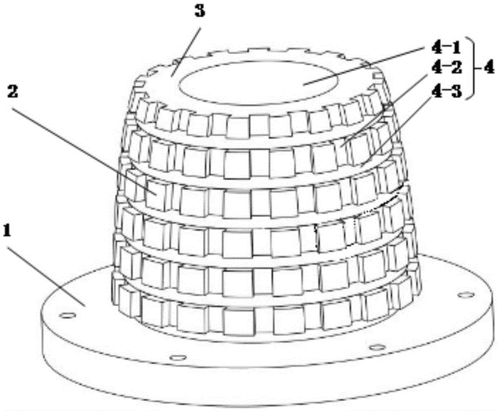
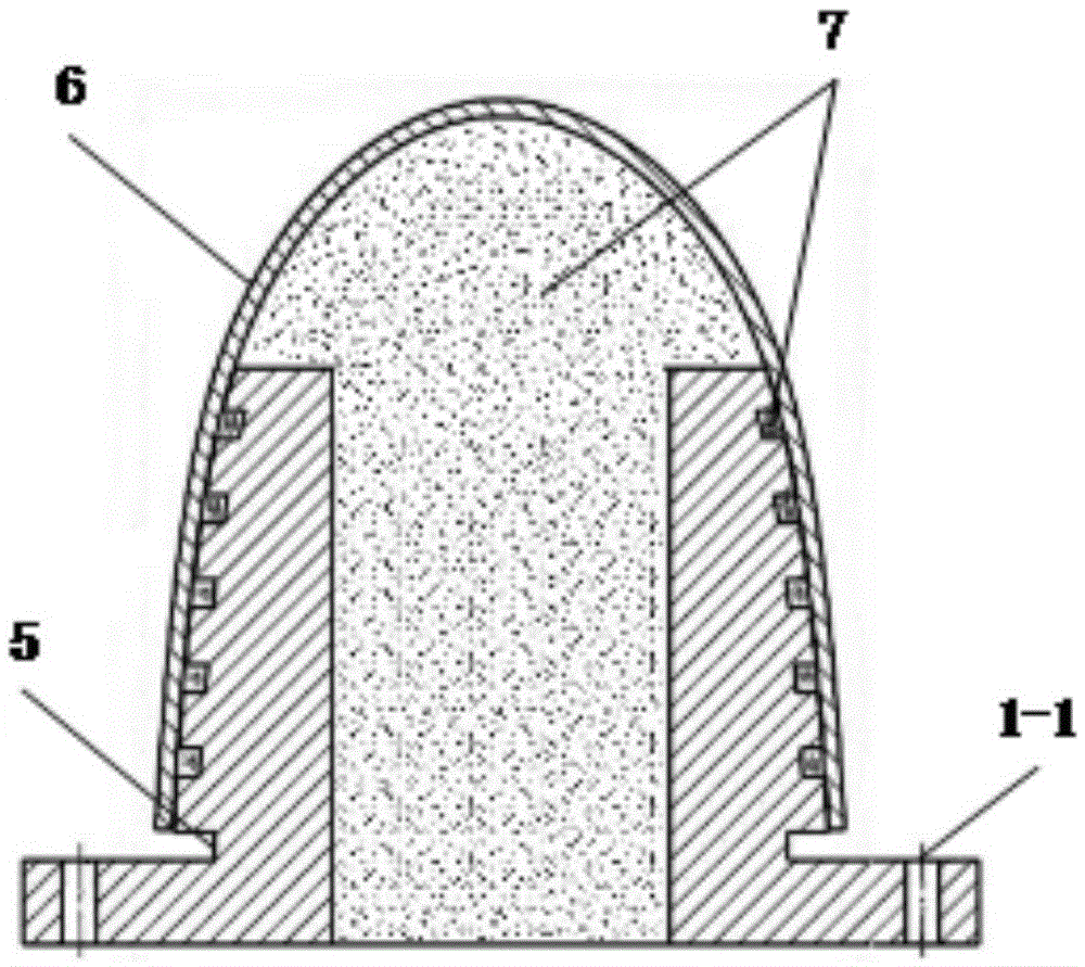
[0016] Specific implementation mode one: as Figure 1~2 As shown, the clamping device for the precision machining of the outer surface of the conformal fairing in this embodiment includes a base 1, a clamping base 3 and several contact units 2, the base 1 is a circular base, and the clamping base 3 is a cylinder shape, one end of the clamping base 3 is fixed on one end surface of the base 1, and on the outer wall of the clamping base 3 there are several contact units 2 arranged in a matrix along its circumferential direction and its axial direction. The outer surfaces are all on the same curved surface, and the curve equation of the curved surface is consistent with the curve equation of the inner surface of the conformal fairing 6, a longitudinal through groove 4-2 is formed between two adjacent rows of contact units 2, and two adjacent rows A transverse channel 4-3 is formed between the contact units 2, and the longitudinal channel 4-2 and the transverse channel 4-3 are inte...

specific Embodiment approach 2

[0017] Specific implementation mode two: as figure 1 As shown, the contour of the contact surface of the contact unit 2 in this embodiment is polygonal or circular. Such a design is used for direct contact with the conformal fairing 6, and the curve equation of the curved surface is consistent with the curve equation of the inner surface of the conformal fairing 6, which reduces the local stress concentration after the conformal fairing 6 is clamped. Other components and connections are the same as those in the first embodiment.

specific Embodiment approach 3

[0018] Specific implementation mode three: as figure 1 As shown, the contact surface profile of the contact unit 2 in this embodiment is rectangular, trapezoidal or triangular. Such a design is used for direct contact with the conformal fairing 6, and the curve equation of the curved surface is consistent with the curve equation of the inner surface of the conformal fairing 6, which reduces the local stress concentration after the conformal fairing 6 is clamped. Other components and connections are the same as those in the second embodiment.


PUM


Abstract

The invention discloses a clamping device and method used for precise machining of the outer surface of a shape-preserving fairing and relates to a clamping device and method. The problem that according to an existing clamping device and method for the outer surface of a shape-preserving fairing, the inner surface of the fairing is completely attached to the clamping device, and consequently the machining precision is low is solved. A plurality of contact units are arranged on the outer side wall of a clamping base body in the circumferential direction and the axial direction of the clamping base body in a matrix manner. The outer surfaces of the multiple contact units are located on the same curved face. The curve equation of the curved face is consistent with the curve equation of the inner surface of the shape-preserving fairing. A filling unit is formed by a center through hole, a longitudinal through groove and a transverse through groove of the clamping base body jointly. The contact units and the clamping base body are fixedly and integrally installed. An annular groove is machined in the position, connected with a base, on the clamping base body. The method includes the first step of fixing of the fairing, the second step of inverted filling and the third step of connecting and fixing after solidification. The clamping device and method are used for precision machining of the outer surface of the shape-preserving fairing.

Description

technical field [0001] The invention relates to a clamping device and a clamping method for precise machining of the outer surface of a conformal fairing, and belongs to the technical field of machining clamping devices. Background technique [0002] In order to adapt to the development of high-speed aircraft and balance the aerodynamic requirements of the aircraft, the contradiction between stealth and optical performance, conformal optical components came into being, that is, to smoothly adapt to the external shape of the system platform for the purpose of improving the aerodynamic performance of the system optical window. The primary key element in the application of conformal optical components is the fairing of the aircraft. Compared with the traditional hemispherical fairing, the conformal fairing can significantly reduce the flight resistance of the aircraft, improve the air flow field around the aircraft, and reduce the aero-optic effect on the image quality inside ...

Claims


Application Information

Patent Timeline
Patent Type & Authority Applications(China)
IPC IPC(8): B23Q3/12
CPCB23Q3/12
Inventor 郭兵赵清亮张春雨王金虎顾兴士孙金霞陈洪许
Owner HARBIN INST OF TECH
Why Eureka
Eureka Blog
Learn More