Automatic constant-temperature ink filling device for printer

A technology for automatic inking and printer use. It is used in general parts of printing machinery, printing presses, rotary printing presses, etc. It can solve the problems of oil black adding ink oxidation drying, time, waste of ink substrate, and unstable printing effect. , to achieve better printing effect, improve the quality of printed matter, and improve the effect of ink utilization.

Inactive Publication Date: 2016-06-01
邓泳安
View PDF9 Cites 2 Cited by
  • Summary
  • Abstract
  • Description
  • Claims
  • Application Information

AI Technical Summary

Problems solved by technology

[0002] In the existing screen printing process, people usually add ink to the screen manually "a small amount and many times". If the screen ink is not added in time or too little, the ink will be broken, and the equipment needs to be turned on and restarted, which will affect the quality of the printed product. It may even cause the product to be scrapped, and the preparation work for restarting the machine will also cause waste of time, ink, and substrate; if the ink black is added too frequently or too much, the ink will oxidize and dry due to the excessive exposure of the ink to the air, and the printed matter will be damaged. There are quality problems such as trachoma, so in order to obtain high-quality printed products, it is very necessary to realize automatic ink addition, and in order to ensure the consistency of the appearance and performance of the crafts to be printed, the control of ink viscosity is an indispensable part of obtaining high-quality printed products
[0003] However, the printing effect of existing ink printers is not stable enough, and its printing effect fluctuates due to changes in ambient temperature. This problem needs to be solved urgently

Method used


Image

  • Automatic constant-temperature ink filling device for printer

Examples


Embodiment Construction

[0018] The following describes the embodiments of the present invention in detail with reference to the accompanying drawings, but the present invention can be implemented in a variety of different ways defined and covered by the claims.

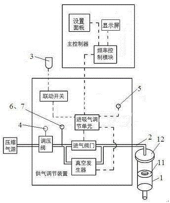
[0019] See figure 1 A constant temperature automatic ink refilling device for a printer includes an air supply adjusting device, a main controller electrically connected to the air supply adjusting device, and an ink storage cylinder 1 connected to the air supply adjusting device through a ventilation pipe. The ink storage cylinder 1 is The inner cavity of the cylinder is plugged with a syringe structure of a piston 11. The piston 11 can prevent ink from entering the ventilation pipe 2. One end of the ink storage cylinder 1 is connected with the ventilation pipe 2, and the air supply regulator blows the ink storage cylinder 1 through the ventilation pipe 2 Air or suction, the other end of the ink storage cylinder 1 is provided with an ink outl...


PUM


Abstract

The invention discloses an automatic constant-temperature ink filling device for a printer. The automatic constant-temperature ink filling device comprises an air supply adjusting device, a main controller and an ink storage cartridge, wherein the main controller is electrically connected with the air supply adjusting device; the ink storage cartridge is connected with the air supply adjusting device through an air pipe; the ink storage cartridge is of a needle cylinder type structure that a piston is plugged in an inner cavity of a cartridge body; one end of the ink storage cartridge communicates with the air pipe, and the air supply adjusting device blows air to the ink storage cartridge or generates suction negative-pressure through the air pipe; the other end of the ink storage cartridge is provided with an ink outlet, and the ink outlet is connected with a screen printing machine and supplies ink for the screen printing machine; an electric constant temperature system and a stirring system are arranged in the ink storage cartridge; the electric constant temperature system is used for controlling the temperature of the ink in the ink storage cartridge to be within the range of 25-30 DEG C; the stirring system is used for stirring the ink in the ink storage cartridge every two hours. By adopting the automatic constant-temperature ink filling device, the printing effect of the printer is stable and does not change with the environmental temperature.

Description

Technical field [0001] The invention relates to screen printing equipment, and in particular, to a constant temperature automatic ink adding device for printers that can control ink viscosity. Background technique [0002] In the existing screen printing process, people usually add ink to the screen in a "small amount of times" manually. If the screen ink is not added in time or added too little, it will cause the ink to be cut off. The device needs to be restarted, which affects the printing quality. Even the product is scrapped, and the preparation work for restarting will also waste time, ink, and substrate; if oil black is added too frequently or too much, the ink will oxidize and dry out due to excessive exposure of the ink to the air. There are quality problems such as blisters, so in order to obtain high-quality prints, it is necessary to automatically add ink, and in order to ensure the consistency of the appearance and performance of the handicrafts to be printed, the c...

Claims


Application Information

Patent Timeline
Patent Type & Authority Applications(China)
IPC IPC(8): B41F31/02B41F15/14
CPCB41F31/02B41F15/14
Inventor 邓泳安
Owner 邓泳安
Why Eureka
Try Eureka