Full-hydraulic electric stacking forklift
An electric stacker, full hydraulic technology, applied in the field of stacker, can solve the problems of narrow high-efficiency area of motor, low power factor of AC motor, decrease of discharge current capacity of lead-acid battery, etc., so as to improve discharge capacity efficiency and reduce hydraulic pressure. System noise, the effect of avoiding throttling speed loss
- Summary
- Abstract
- Description
- Claims
- Application Information
AI Technical Summary
Problems solved by technology
Method used
Image
Examples
specific Embodiment approach
[0047] The conception, specific structure and technical effects of the present invention will be further described below in conjunction with the accompanying drawings, so as to fully understand the purpose, characteristics and effects of the present invention.
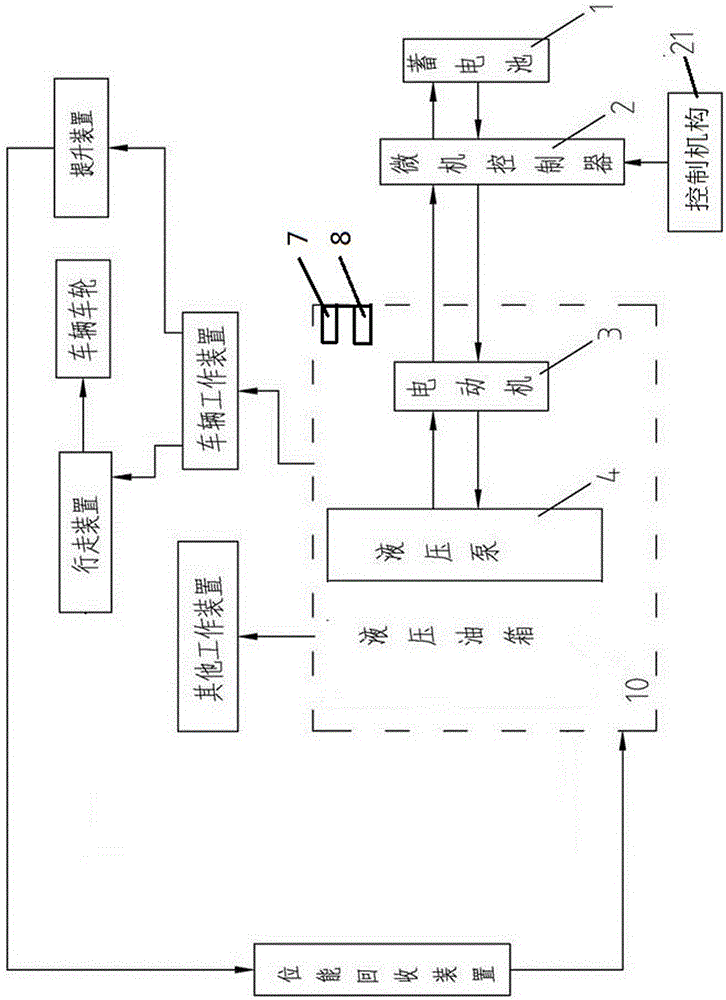
[0048] A full hydraulic electric stacker of the present invention is composed of a storage battery 1 for a power source, a microcomputer controller 2, a control mechanism 21, an electric motor 3, a hydraulic pump 4, a hydraulic oil tank 10, a vehicle working device, a traveling device, and a lifting device , travel speed limiting device, potential energy recovery device and wheels. The basic working principle of the present invention is: the rotation of the electric motor is driven by the storage battery, and the hydraulic pump is driven by the electric motor to work. 31, the oil circuit 2-4 and the oil pipe 35 of the oil pump 33, the oil pipe 33, the traveling reversing valve 13 are directly connected with the oil tan...
Embodiment 1
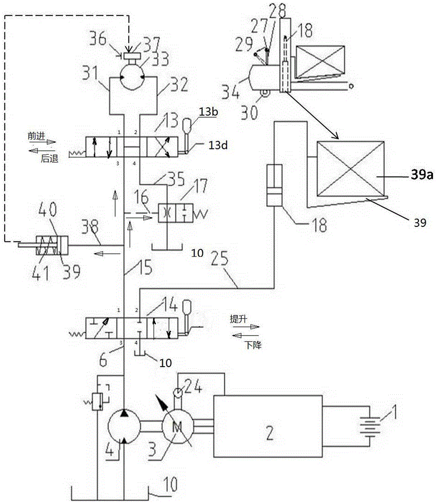
[0050] This embodiment is a basic structure, see figure 2 shown. There is no special description in each embodiment of the present invention, and the reversing valves used are all three-position four-way valves. In the embodiment (note: the second and third embodiments are also the same), the walking manual reversing valve 13 is positioned by a steel ball, and the lifting manual reversing valve 14 is positioned by a spring. The walking acceleration is realized by the potentiometer 14d of the rotating handle 14b; and the lifting acceleration is realized by the manual potentiometer 14d on the handle 14b.
[0051] (1) Operation of the running gear:
[0052] 1. Run in forward direction:
[0053] When the direction handle 27 is pressed according to the direction of the arrow 29; the walking manual reversing valve 13 is placed in the "forward" position; The handle 13d rotates to send an acceleration signal to the microcomputer controller 2, and the microcomputer controller 2 ou...
Embodiment 2
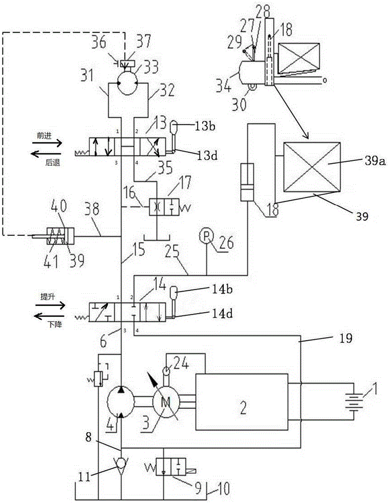
[0068] This embodiment is an improvement on the basis of Embodiment 1, adding the function of recycling the heavy load potential energy drop, see image 3 shown. This embodiment is also realized through the control of the walking manual reversing valve 13 and the lifting manual reversing valve 14. Since the basic structure is the same, the repeated parts will not be repeated. The difference between the present invention and the first embodiment is: 1) The regeneration solenoid valve 9 and the one-way valve 11 are connected in parallel, and connected between the oil cylinder 18 and the oil tank 10 through the pipeline 19 and the lifting manual reversing valve 14 passage 2-4 . 2) Add a pressure sensor 26 for controlling the regeneration solenoid valve 9 .
[0069] Lifting device operation:
[0070] 1. Cargo lifting operation;
[0071] When the lifting manual reversing valve 14 is in the "lift" position, the walking manual reversing valve 13 is in the middle position (at the ...
PUM
 Abstract
Description
Claims
Application Information
 - R&D
- Intellectual Property
- Life Sciences
- Materials
- Tech Scout
- Unparalleled Data Quality
- Higher Quality Content
- 60% Fewer Hallucinations
Browse by: Latest US Patents, China's latest patents, Technical Efficacy Thesaurus, Application Domain, Technology Topic, Popular Technical Reports.
© 2025 PatSnap. All rights reserved.Legal|Privacy policy|Modern Slavery Act Transparency Statement|Sitemap|About US| Contact US: help@patsnap.com


