Clothes treating apparatus with heat pump cycle

A technology of clothes treatment device and heat pump cycle, which is applied to washing devices, other drying devices, household appliances, etc., can solve the problems of evaporator dehumidification performance limitation, increase extra cost, etc., so as to improve dehumidification performance, improve performance and reliability. stable effect

Inactive Publication Date: 2016-06-01
LG ELECTRONICS INC
View PDF5 Cites 11 Cited by
  • Summary
  • Abstract
  • Description
  • Claims
  • Application Information

AI Technical Summary

Problems solved by technology

[0014] However, the existing method of installing a sub-condenser and forming an independent flow path will increase additional costs, and because the heat dissipation of the condenser is discharged to the outside, there is a limit to directly improving the dehumidification performance in the evaporator.

Method used


Image

  • Clothes treating apparatus with heat pump cycle
  • Clothes treating apparatus with heat pump cycle
  • Clothes treating apparatus with heat pump cycle

Examples


no. 1 example

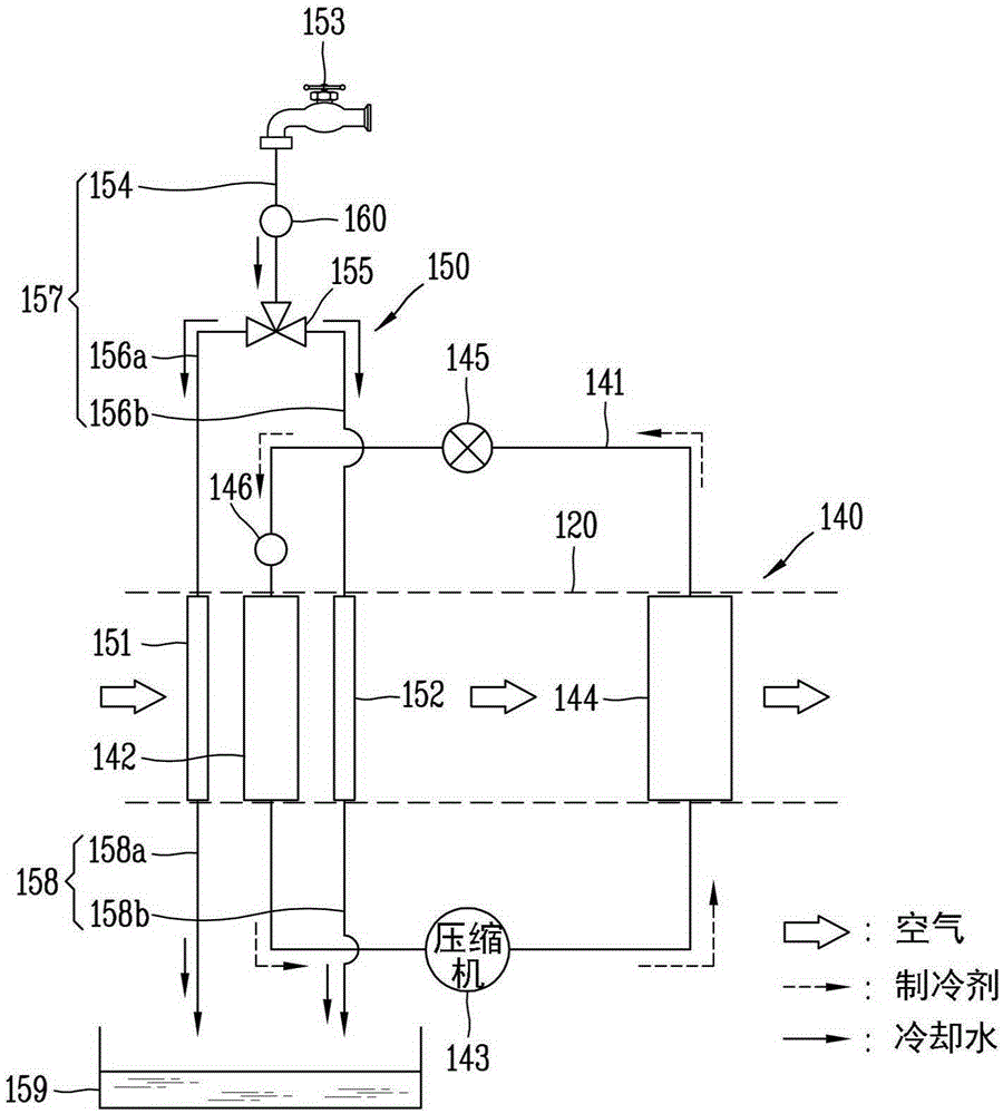
[0076] image 3 It is a schematic diagram showing the dehumidification system 150 of the first embodiment of the present invention.

[0077] The heat exchanger of the first embodiment is a water-cooled heat exchanger. The water-cooled heat exchanger may be a finned tube heat exchanger.

[0078] image 3 The illustrated plurality of heat exchangers may be constituted by a first water-cooled heat exchanger 151 arranged on the upstream side of the evaporator 142 and a second water-cooled heat exchanger 152 arranged on the downstream side of the evaporator 142 .

[0079] The dehumidification system 150 may include: a water supply unit 153, which supplies water to the first water-cooled heat exchanger 151 and the second water-cooled heat exchanger 152; a water supply pipe 157, which forms a water supply flow path to supply water to each heat exchanger respectively; The pipe 158 forms a drain flow path for draining water from each heat exchanger.

[0080] The water supply unit 1...

no. 2 example

[0095] Figure 4 It is a schematic diagram showing the dehumidification system of the second embodiment of the present invention.

[0096] Figure 4 The shown first water-cooled heat exchanger 251 and second water-cooled heat exchanger 252 are connected via a first connecting pipe 261 . The other end of the first distribution pipe 256a branched from the main water supply pipe 254 is connected to the image 3 The illustrated first distribution pipe 156a is differently connected to the downstream side of the first connection pipe 261 (based on the cooling water moving direction). One drain pipe 258 is connected to the first water-cooled heat exchanger 251 . Other structural elements are the same as or similar to those of the first embodiment, and therefore, detailed descriptions are omitted for clarity of description.

[0097] The movement path of the cooling water according to the temperature of the supplied water in the second embodiment will be described.

[0098]When th...

no. 3 example

[0101] Figure 5 It is a schematic diagram showing the dehumidification system of the third embodiment of the present invention.

[0102] Figure 5 The shown first water-cooled heat exchanger 351 and second water-cooled heat exchanger 352 are connected via a second connecting pipe 361 . The water supply pipe 357 is not composed of image 3 The shown main water supply pipe 154 , distribution pipes, etc. are constituted, and are directly connected to the first water-cooled heat exchanger 351 . Also, the drain pipe 358 may be connected only to the second water-cooled heat exchanger 352 . In this case, the first temperature sensor may be omitted.

[0103] The cooling water movement path and the action of the cooling water in the third embodiment will be described.

[0104] Cooling water flows into the first water-cooled heat exchanger 351 through the water supply pipe 357, and in the first water-cooled heat exchanger 351, the sensible heat and latent heat of the air to flow i...


PUM


Abstract

A clothes treating apparatus that includes a heat pump cycle and a dehumidifying device is provided herein. The clothes treating apparatus may include a case and a drum installed within the case and configured to accommodate an item for drying. A circulation duct may be provided to form an air circulation flow channel that allows air to circulate through the drum. The heat pump cycle may include an evaporator and a condenser disposed to be spaced apart from one another within the circulation duct, the heat pump cycle being configured to absorb heat of air released from the drum through the evaporator and transmit the absorbed heat to air introduced to the drum through the condenser, by using a working fluid that circulates by way of the evaporator and the condenser. Moreover, the dehumidification device may be provided to dehumidify air passing through the evaporator in the circulation duct.

Description

technical field [0001] The present invention relates to a laundry treating device having a heat pump cycle, and more particularly, to a stable laundry treating device capable of improving dehumidification performance and facilitating circulation. Background technique [0002] Generally, a clothes processing device with a drying function such as a washing machine or a dryer puts the laundry in the state of completing the washing and dehydration process into the drum, and supplies hot air to the inside of the drum to evaporate the moisture of the laundry for drying. Device for washing. [0003] Clothes dryers can be classified into exhaust-type clothes dryers and condensation-type clothes dryers according to the treatment method of the humid air passing through the drum after drying the laundry. [0004] The exhaust type clothes dryer discharges the humid air that comes out of the drum to the outside of the dryer, and the condensation type clothes dryer does not discharge the...

Claims


Application Information

Patent Timeline
Patent Type & Authority Applications(China)
IPC IPC(8): D06F58/20D06F58/28D06F34/24D06F58/38
CPCD06F58/206D06F58/38D06F2103/08D06F2103/36D06F2105/24D06F2103/50D06F2105/26D06F58/24D06F2105/02D06F34/24D06F2103/16D06F39/12D06F2105/32D06F37/26D06F59/02
Inventor 柳秉助金钟锡李勇柱
Owner LG ELECTRONICS INC
Why Eureka
Try Eureka