A plunger pump valve group

A plunger pump and valve group technology, which is applied to pump components, variable displacement pump components, components of pumping devices for elastic fluids, etc., can solve the problems of high material consumption, large hydraulic end dimensions, and valve gap Problems such as high flow rate, to achieve the effect of improving pump efficiency, saving raw materials, and reducing valve gap flow rate

Active Publication Date: 2018-06-29
NINGBO HELI MECHANICAL PUMP CO LTD
View PDF4 Cites 3 Cited by
  • Summary
  • Abstract
  • Description
  • Claims
  • Application Information

AI Technical Summary

Problems solved by technology

Conventionally designed valve groups are single-guided, double-guided, flat valves, cone valves, claw valves, ball valves, cylinder valves, knife valves and other valves of different shapes, but they all have the same fluid flow direction, usually called one-way valves. Runner valve, the valve slit flow rate of this valve group is generally high, because the valve slit flow rate is the main index of valve work, so the shape and size of the valve in the design are relatively large due to the limitation of the valve slit flow rate, that is, for The reason why the overall size of the liquid end is large and consumes a lot of materials

Method used


Image

  • A plunger pump valve group
  • A plunger pump valve group
  • A plunger pump valve group

Examples


Embodiment Construction

[0016] The present invention will be further described in detail below in conjunction with the accompanying drawings and embodiments.

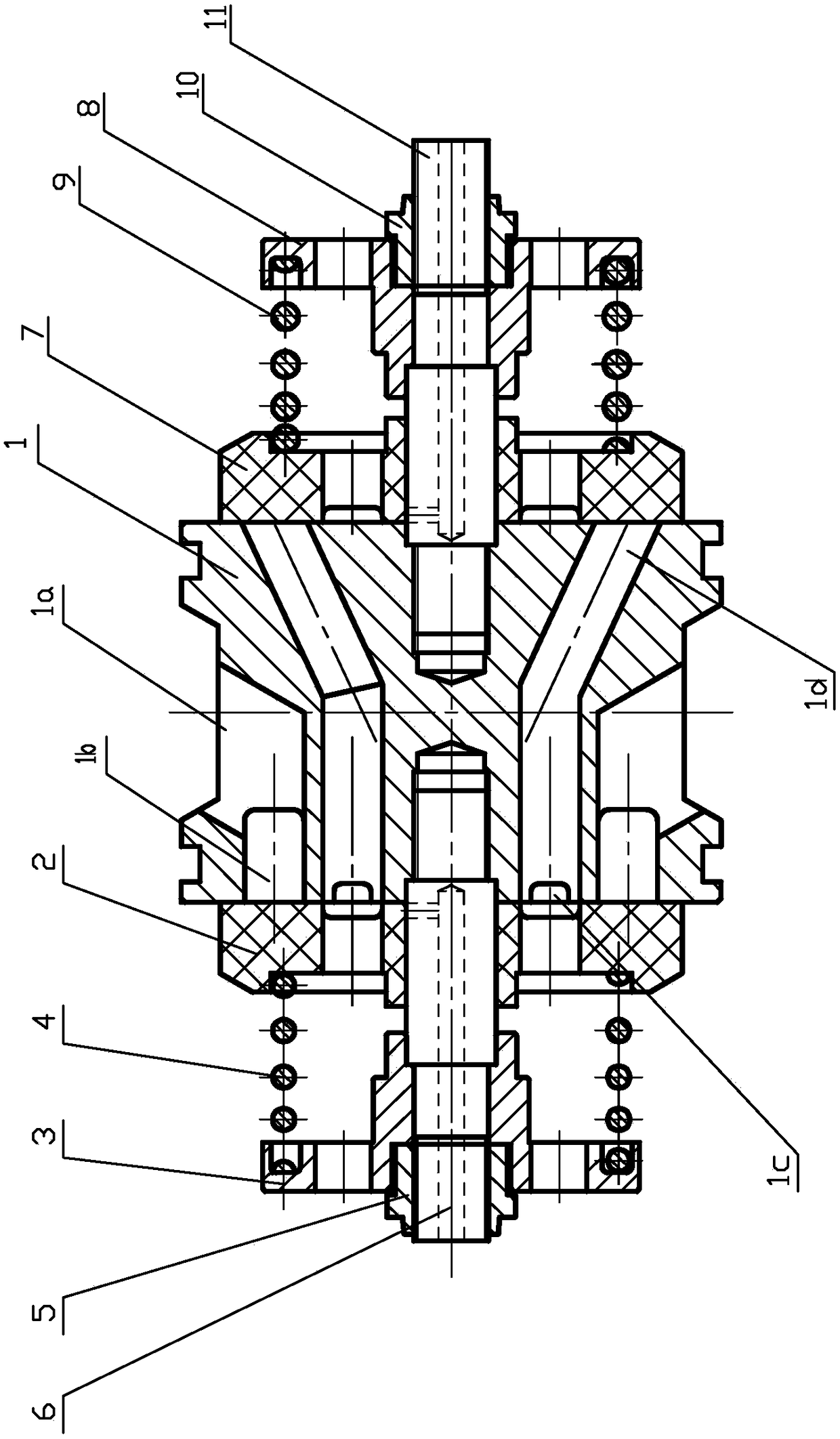
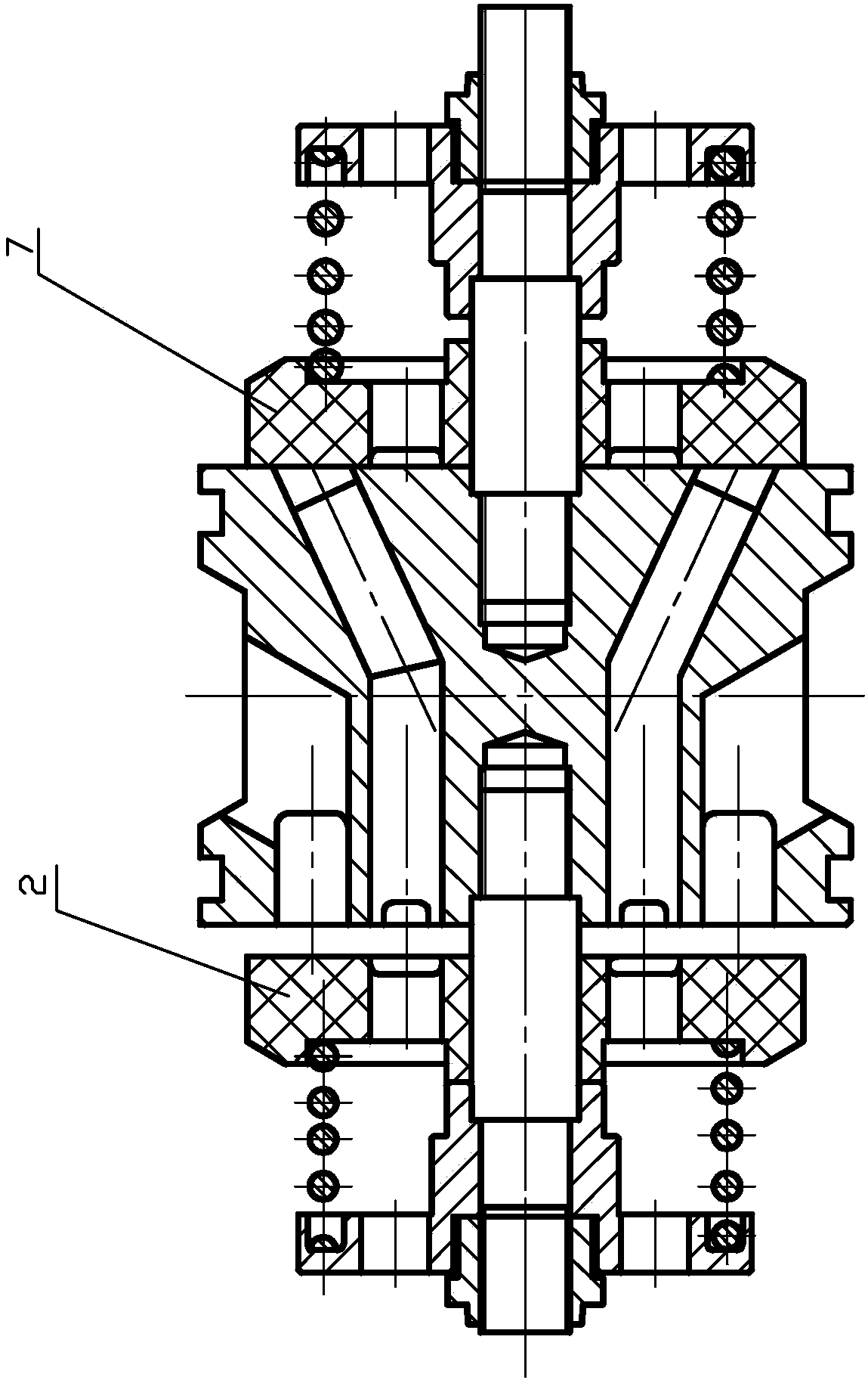
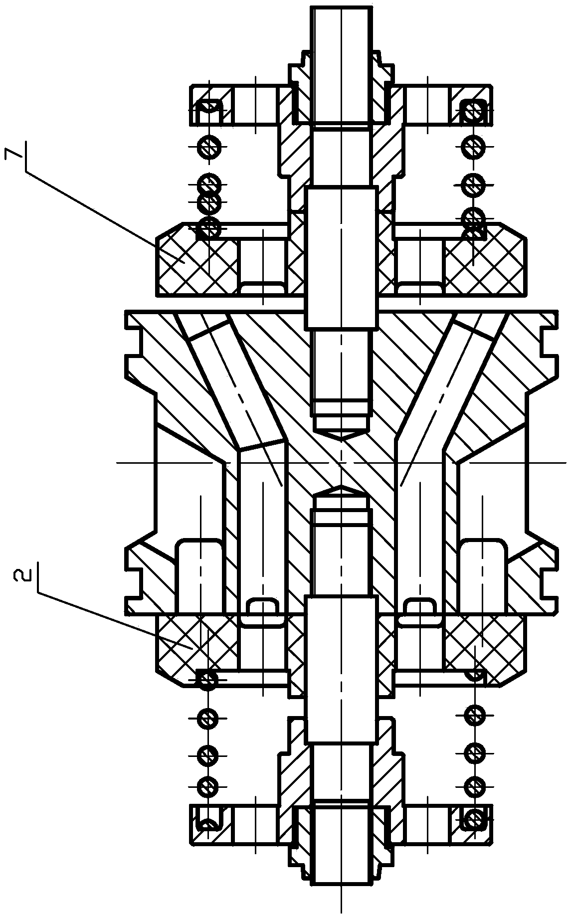
[0017] Such as figure 1 The plunger pump valve group shown includes valve seat 1, liquid inlet valve plate 2, liquid inlet spring seat 3, suction spring 4, first lock nut 5, suction valve screw rod 6, liquid discharge valve plate 7, Drain spring seat 8, discharge spring 9, second lock nut 10, discharge valve screw rod 11.

[0018] Wherein, both ends of the valve seat are planes, wherein one end plane of the valve seat is the liquid inlet plane, and the other end plane of the valve seat is the liquid discharge plane; the liquid inlet valve plate 2 is located on the side of the liquid inlet plane outside the valve seat 1 , The drain valve plate 7 is located on the side of the drain plane outside the valve seat 1.

[0019] The outer wall of the valve seat 1 is provided with a liquid inlet chamber 1a, and the liquid inlet chamber 1a can be set a...


PUM


Abstract

The invention relates to a plunger pump valve bank which comprises a valve seat. The plunger pump valve bank is characterized in that liquid inlet cavities are formed in the outer wall of the valve seat, the two end faces of the valve seat are both planes, the plane at one end of the valve seat is the liquid inlet plane, and the plane at the other end of the valve seat is the drainage plane; the liquid inlet plane is provided with an annular groove communicating with the liquid inlet cavities; a liquid inlet valve plate is arranged outside the liquid inlet plane of the valve seat and provided with liquid inlets, and a sealing surface is located between the outer edge of the liquid inlet valve plate and the outer edge of the liquid inlet plane; the liquid inlet plane is provided with drainage cavities, and the drainage cavities and the annular groove are arranged at intervals; the drainage plane is provided with liquid outlet cavities, and drainage channels enabling the drainage cavities and the liquid outlet cavities to communicate are formed in the valve seat; a drainage valve plate is arranged outside the drainage plane of the valve seat and provided with drainage holes, and a sealing surface is located between the outer edge of the drainage valve plate and the outer edge of the drainage plane. The plunger pump valve bank provided by the invention is small in size, high in pump efficiency and capable of effectively lowering the valve play flow rate.

Description

technical field [0001] The invention relates to a plunger pump valve group. Background technique [0002] The main components of the reciprocating plunger pump are power, hydraulic power, and power source to form an assembly into a reciprocating plunger pump. The main parts of power are crankshaft, fuselage, connecting rod, crosshead and connecting rod. The hydraulic main parts are pump body, box body, plunger, packing, guide sleeve, inlet and outlet valve group, inlet water collector, and outlet assembly. The power source is composed of electric motor (diesel engine), reducer (drive pulley, drive belt), shield, base and so on. The reciprocating plunger pump is a positive displacement pump with high pressure, low flow rate and high efficiency. In the case of the same power, the pressure is high and the flow rate is small. On the contrary, the flow rate is large and the pressure is small. The power mechanism is basically similar, and the hydraulic mechanism changes greatly...

Claims


Application Information

Patent Timeline
Patent Type & Authority Patents(China)
IPC IPC(8): F04B53/10
CPCF04B53/1022F04B53/1035F04B53/1087F04B53/109
Inventor 陈明海陈英峰朱海波匡伐
Owner NINGBO HELI MECHANICAL PUMP CO LTD
Why Eureka
Try Eureka