
Rotary valve type pump protecting device

A protection device, rotary valve technology, applied in non-variable-capacity pump, pump control, machine/engine, etc., can solve the problems of unadjustable bypass fluid pressure, increase investment, etc., achieve simple structure, prevent "water hammer". Effect

Inactive Publication Date: 2016-06-01
WUHUAN ENG
View PDF7 Cites 4 Cited by
  • Summary
  • Abstract
  • Description
  • Claims
  • Application Information

AI Technical Summary

Problems solved by technology

So far, the opening of the bypass is usually manual. If it is changed to automatic control, it is necessary to design a control system, thereby increasing investment.
And the pressure of the bypass fluid is not adjustable

Method used


Image

  • Rotary valve type pump protecting device
  • Rotary valve type pump protecting device
  • Rotary valve type pump protecting device

Examples


Embodiment Construction

[0013] Below in conjunction with accompanying drawing, the present invention will be further explained:

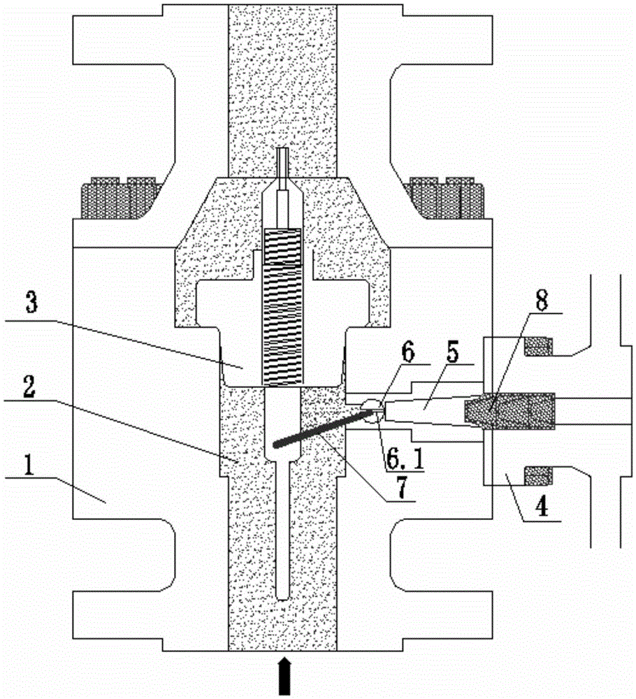
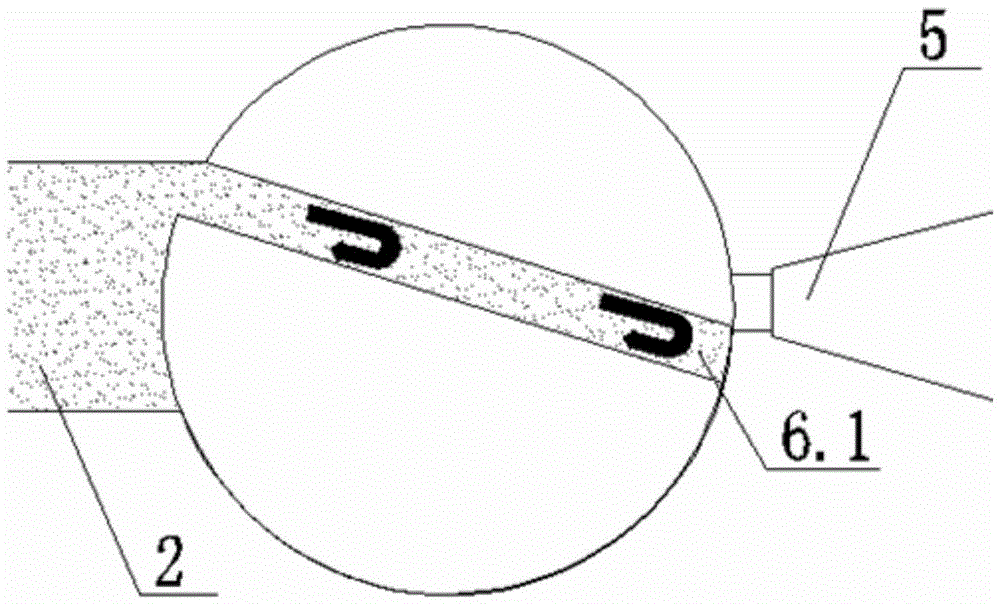
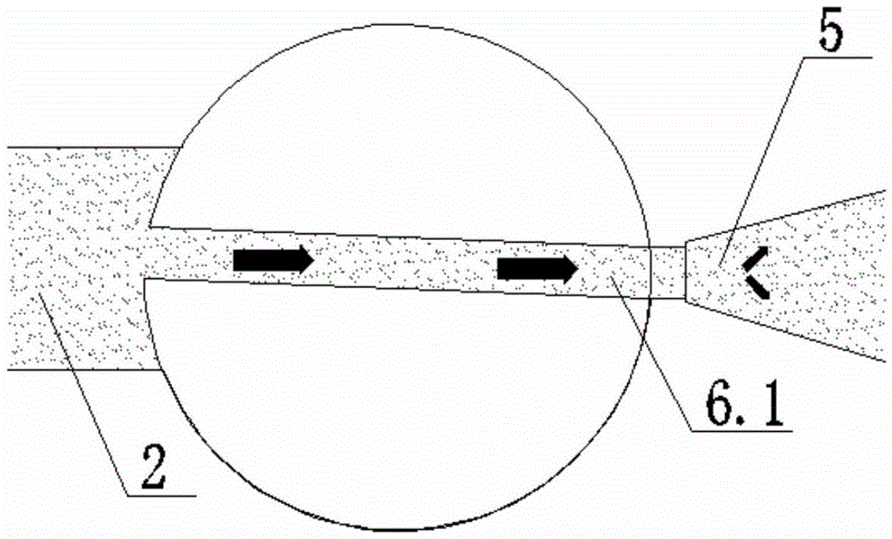
[0014] see figure 1 , the outlet of the centrifugal pump (not shown in the figure) is provided with a sealing valve body 1, and a check valve 3 is provided in the first flow channel 2 inside the sealing valve body 1, and the first flow channel below the check valve 3 The channel 2 communicates with the second flow channel 5 through the flow hole 6.1 of the ball valve 6; the second flow channel 5 is located in the bypass valve body 4, the ball valve 6 is fixedly connected to one end of the guide rod 7, and the guide rod The other end of 7 is hinged with check valve 3. When check valve 3 is displaced, one end of guide rod 7 can drive ball valve 6 to rotate by pulling the other end of guide rod 7. A multi-stage throttling orifice 8 is also provided in the second flow channel 5 .

[0015] working principle:

[0016] When the centrifugal pump starts, the downstream flow cont...


PUM


Abstract

The invention discloses a rotary valve type pump protecting device. The problems that an existing pump protecting device is complex to operate and high in equipment investment, and safety needs to be further improved are solved. According to the technical scheme, the rotary valve type pump protecting device comprises a sealing valve body with a first flow channel, and a check valve is arranged in the first flow channel; the device further comprises a bypass valve body with a second flow channel, and the part, blow the check valve, of the first flow channel communicates with the second flow channel through a flow hole in a ball valve; the ball valve is fixedly connected with one end of a guide rod, and the other end of the guide rod is hinged to the check valve. The rotary valve type pump protecting device is simple in structure, free of manual operation, controllable in pressure, low in cost, efficient and safe.

Description

technical field [0001] The invention relates to a pump protection device, in particular to a rotary valve type pump protection device. Background technique [0002] In order to meet the flow requirements of the process, the flow of the centrifugal pump system usually fluctuates within a certain range. Too small flow will often cause the temperature of the centrifugal pump to be too high, the operation will be unstable, and a lot of noise will be generated. Therefore, the outlet of the centrifugal pump is usually designed with a bypass. When When the pump is working at low load, the bypass valve is opened to ensure the minimum required flow through the pump, improve the efficiency of the pump and reduce the failure of the pump. So far, the opening of the bypass is usually manual. If it is changed to automatic control, it is necessary to design a control system, thereby increasing investment. Also, the pressure of the bypass fluid is not adjustable. Therefore, there is an ur...

Claims


Application Information

Patent Timeline
Patent Type & Authority Applications(China)
IPC IPC(8): F04D15/00
CPCF04D15/0077
Inventor 张洪伟沈菊武丽娜江大波蔡晓峰刘三军段中华
Owner WUHUAN ENG
Learn More