Flywheel clutch

A clutch and flywheel technology, applied in the field of flywheel clutches, can solve the problems of inability to drive rotation, large sliding friction, complex structure, etc., and achieve the effect of light weight, fast rotation speed, and not easy to wear

Inactive Publication Date: 2016-06-01
茹咪娜
View PDF6 Cites 2 Cited by
  • Summary
  • Abstract
  • Description
  • Claims
  • Application Information

AI Technical Summary

Problems solved by technology

However, this method of separation and engagement has a complicated structure and is inconvenient to operate; moreover, the sliding friction between the friction wheel and the flywheel is relatively large, and the wear is serious after long-term use, so that it is impossible to realize the driving rotation

Method used


Image

  • Flywheel clutch
  • Flywheel clutch
  • Flywheel clutch

Examples


Embodiment Construction

[0014] In order to enable those skilled in the art to better understand the solutions of the present invention, the technical solutions in the embodiments of the present invention will be clearly and completely described below in conjunction with the drawings in the embodiments of the present invention.

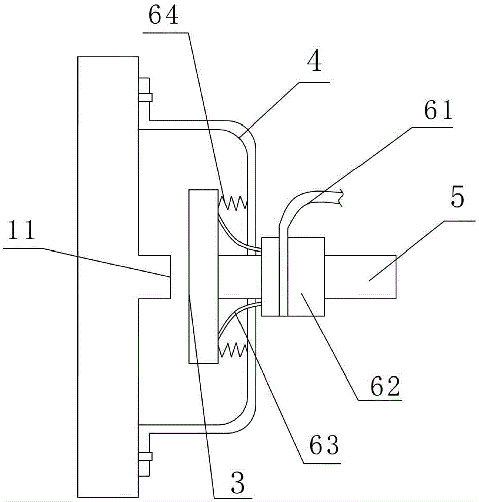
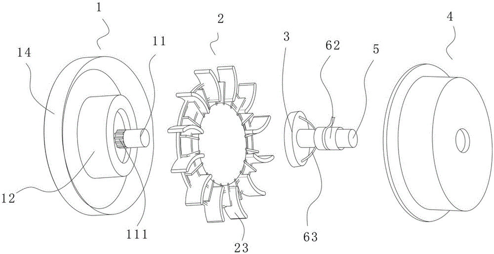
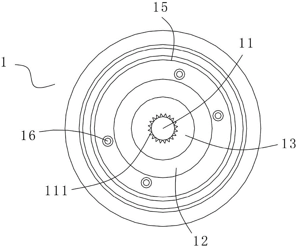
[0015] Such as Figure 1-5 As shown, a flywheel clutch includes a clutch cover 4, a flywheel, a clutch block 3, a gearbox input shaft 5 and a control mechanism, the flywheel is fixedly connected to the clutch cover 4, and the gearbox input shaft 5 is connected to the clutch The block 3 is connected; the control mechanism includes a pull rod 61, a sliding sleeve 62 fixedly connected to the end of the pull rod 61, a separation fork 63 and a compression spring 64; the separation fork 63 is a figure-eight setting for connecting the clutch The block 3 and the sliding sleeve 62, 62 are sleeved on the periphery of the gearbox input shaft 5, and the clutch cover 4 is provided with a ...


PUM


Abstract

The invention discloses a flywheel clutch. The flywheel clutch comprises a clutch cover, a flywheel fixedly connected to the clutch cover, a clutch block, a transmission input shaft fixedly connected to the clutch block, and a control mechanism; the control mechanism includes a pull rod, a slide sleeve fixedly connected to the end part of the pull rod, a separation fork for connecting the clutch block with the slide sleeve, and a pressing spring; the separation fork is splayed; one end part of the pressing spring is connected with the clutch block, and the other end is connected with the clutch cover; the flywheel includes a base molded by pressing an aluminum alloy, and an impeller made of plastic; the base is provided with a mounting column made of an aluminum alloy; the mounting column and the base are integrally molded by die casting; an outer ratchet is formed on the outer surface of the mounting column, and is in rotation stop matching with an inner ratchet of the clutch block; and the length of the outer ratchet is 1 / 3 of the length of the mounting column. A blade is made of plastic, and is not easy to damage; the base is integrally molded by die casting; the flywheel is light in self weight, so that the rotating speed is fast; and the flywheel clutch is low in cost and high in working efficiency.

Description

technical field [0001] The invention belongs to the field of flywheel technology, and in particular relates to a flywheel clutch. Background technique [0002] Flywheels are often used in automobile clutches, which drive the input shaft of the gearbox to rotate through the flywheels. Usually, the clutch is composed of four parts: the driving part, the driven part, the pressing mechanism and the operating mechanism. The main and driven parts and the pressing mechanism are the basic structure to ensure that the clutch is in the engaged state and can transmit power, while the clutch operating mechanism is mainly a device to separate the clutch. The active part is a flywheel, and the driven part is a friction wheel; during the joining process, the distance between the main and driven parts is controlled through the cooperation of the pressing mechanism and the operating mechanism. When the gap between the two is eliminated, the friction wheel is close to the flywheel. The rota...

Claims


Application Information

Patent Timeline
Patent Type & Authority Applications(China)
IPC IPC(8): F16D23/12
CPCF16D23/12
Inventor 茹咪娜
Owner 茹咪娜
Why Eureka
Try Eureka