Nonlinear conical auxiliary spring and air spring
An auxiliary spring, non-linear technology, applied in the direction of springs, spring/shock absorbers, gas shock absorbers, etc., can solve the problems of small vertical stiffness, damage, and affecting the service life of conical auxiliary springs
- Summary
- Abstract
- Description
- Claims
- Application Information
AI Technical Summary
Problems solved by technology
Method used
Image

Examples
Embodiment 1
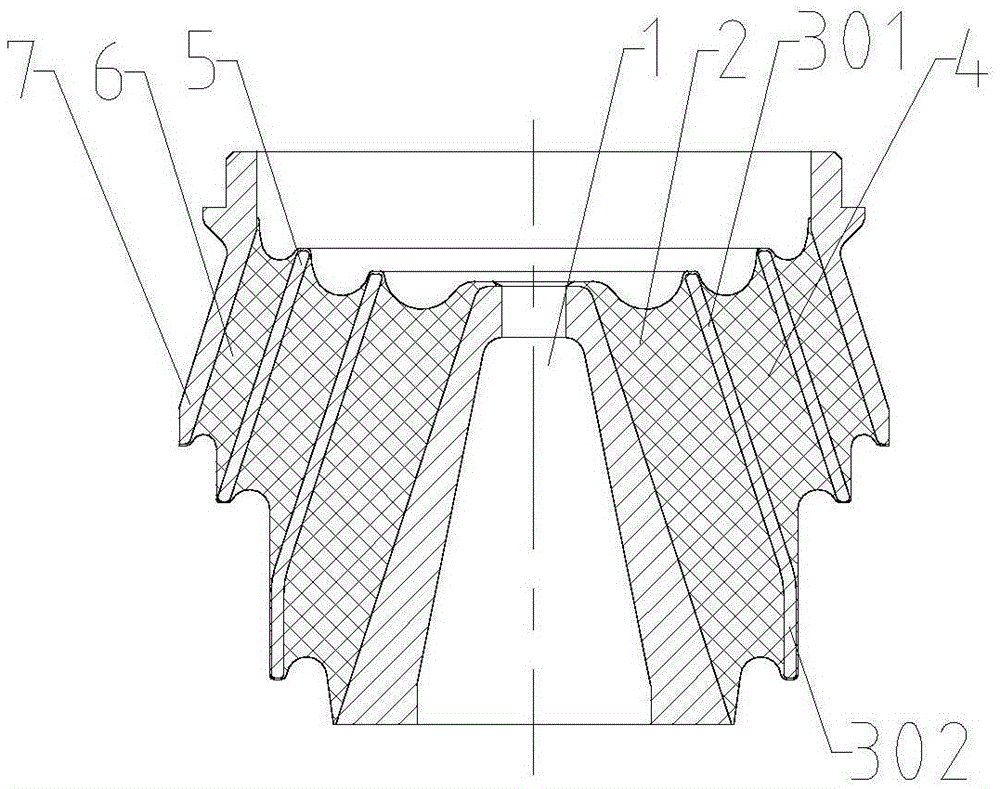
[0020] Such as figure 1 As shown, the non-linear conical auxiliary spring includes a shaft core 1, and the shaft core 1 is a body of revolution in the shape of a truncated cone.
[0021] It also includes an auxiliary spring arranged around the outer peripheral surface of the shaft core 1; the auxiliary spring is a tapered elastic medium, and a rubber layer is used in this embodiment. From the direction close to the outer peripheral surface of the shaft core to the direction away from the outer peripheral surface of the shaft core, there are multiple partition layers arranged at intervals in the rubber layer; the rubber layer is divided into a structure separating the rubber layer and the partition layer, that is, the rubber layer I2, the partition I3, rubber layer II4, separator II5, rubber layer III6 spaced structure. There are 7 layers of coats outside the rubber layer III6.
[0022] Since the shaft core 1 is in the shape of a truncated cone, it includes two upper and low...
Embodiment 2
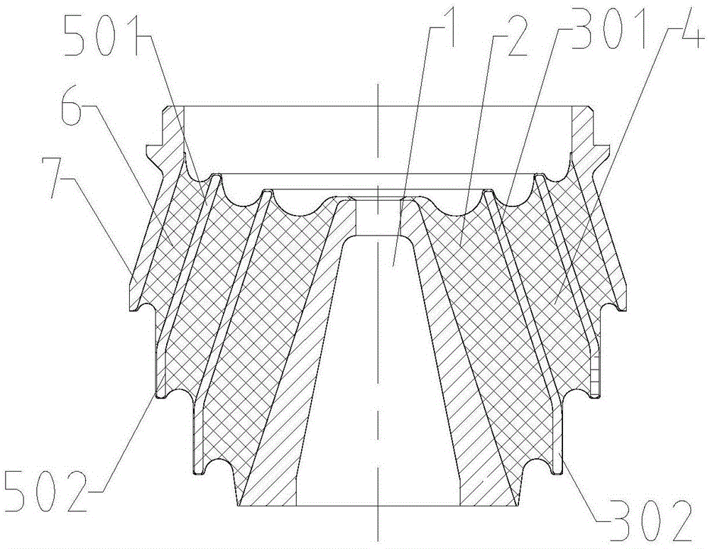
[0026] Such as figure 2 As shown, different from Embodiment 1, the partition II5 also includes a partition section 501 parallel to the outer peripheral surface of the shaft core 1 and a partition section 502 close to the outer peripheral surface of the shaft core, and a section close to the outer peripheral surface of the shaft core 1 The partition section 502 is located on the side close to the wider end surface of the shaft core 1 , that is, the side where the steering system is installed.
[0027] The working principle is the same as that of Embodiment 1. When the vertical load on the side of the vehicle body increases to a certain extent, the partition section 302 contacts the shaft core 1, the partition section 502 contacts the partition 3, and the rubber layer I2 and the rubber layer II4 are no longer involved in vertical deformation.
Embodiment 3
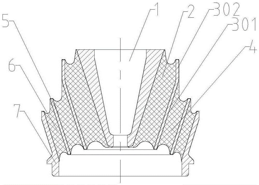
[0029] The difference from Embodiment 1 and Embodiment 2 is that the upper end face of the shaft core 1 with a larger area is the mounting surface on the side close to the vehicle body, and the opposite side is the mounting surface on the side close to the steering system.
[0030] Such as image 3 As shown, the rubber layer I2 is the elastic medium layer closest to the outer peripheral surface of the shaft core 1 , and the separator I3 is the separator layer closest to the outer peripheral surface of the shaft core 1 . Separator 1 includes a section of partition 301 parallel to the outer peripheral surface of the shaft core 1 and a partition section 302 close to the outer peripheral surface of the shaft core, and a section of partition 302 near the outer peripheral surface of the shaft core is located near the wider end surface of the shaft core. side.
[0031] Its working principle is the same as embodiment 1.
PUM
 Abstract
Description
Claims
Application Information
 - R&D
- Intellectual Property
- Life Sciences
- Materials
- Tech Scout
- Unparalleled Data Quality
- Higher Quality Content
- 60% Fewer Hallucinations
Browse by: Latest US Patents, China's latest patents, Technical Efficacy Thesaurus, Application Domain, Technology Topic, Popular Technical Reports.
© 2025 PatSnap. All rights reserved.Legal|Privacy policy|Modern Slavery Act Transparency Statement|Sitemap|About US| Contact US: help@patsnap.com