
Electromagnetic valve with multiple stages of diaphragms

A solenoid valve and diaphragm technology, applied in the field of solenoid valves, can solve the problems of large-area wiring, difficult power supply, poor safety, valve core coil volume, power, and large voltage, etc., to achieve convenient layout, reasonable structural design, good safety effect

Active Publication Date: 2016-06-01
宁波市富金园艺灌溉设备有限公司
View PDF6 Cites 3 Cited by
  • Summary
  • Abstract
  • Description
  • Claims
  • Application Information

AI Technical Summary

Problems solved by technology

[0003] In order to overcome the above-mentioned deficiencies, the purpose of the present invention is to provide a multi-stage diaphragm solenoid valve in the field, so that it can solve the problem of large-area wiring and power supply difficulties in the existing similar products, such as the large volume, power and voltage of the spool coil. Poor technical issues

Method used


Image

  • Electromagnetic valve with multiple stages of diaphragms
  • Electromagnetic valve with multiple stages of diaphragms
  • Electromagnetic valve with multiple stages of diaphragms

Examples


Embodiment Construction

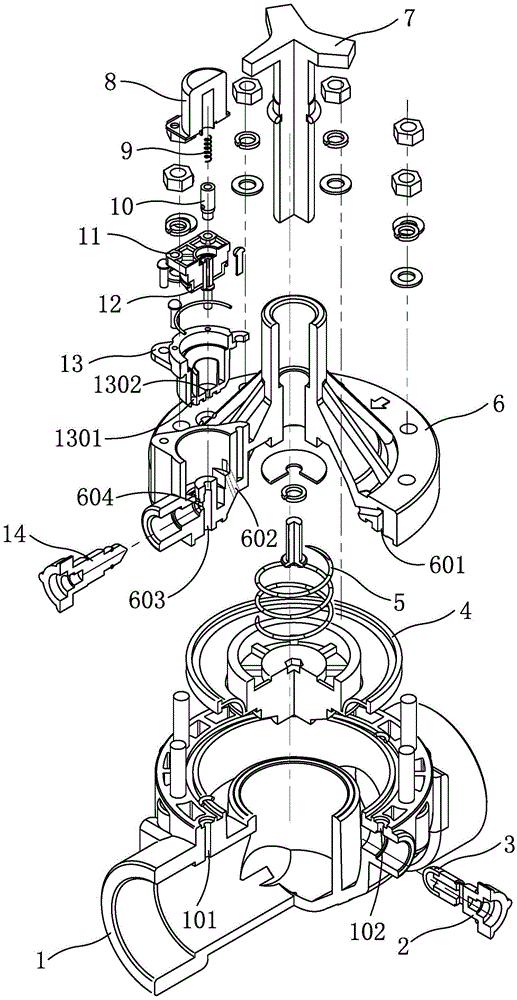
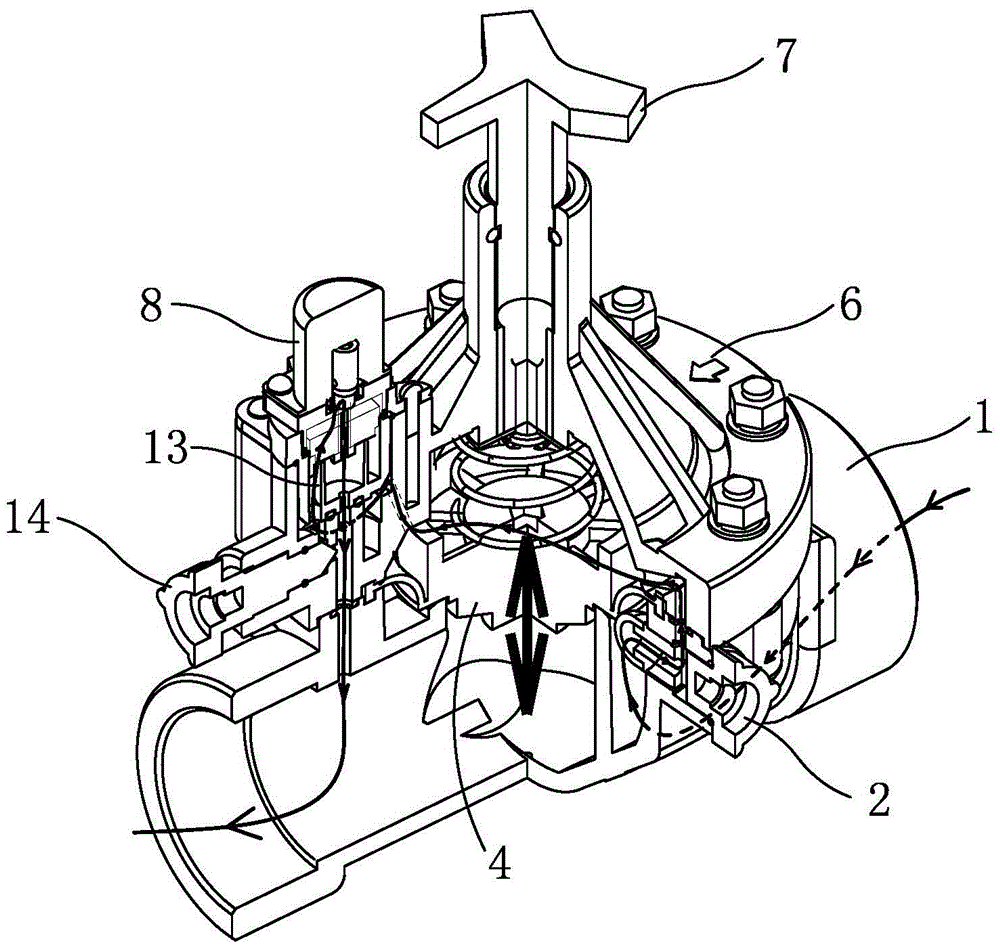
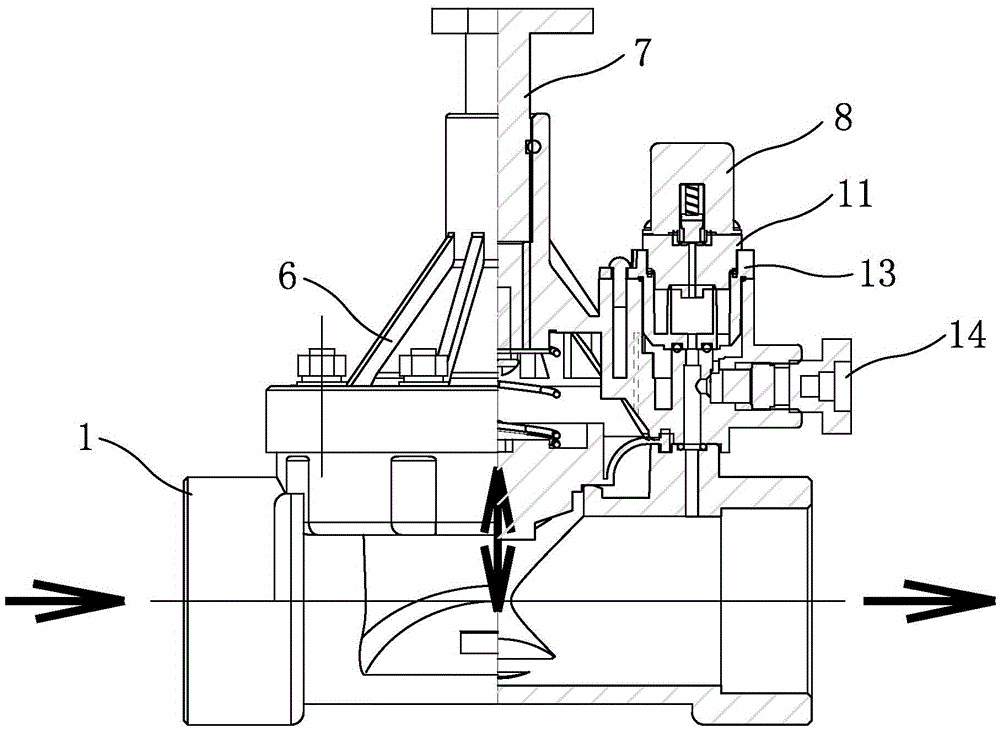
[0025] Now in conjunction with the accompanying drawings, the structure and use of the present invention will be further described. Such as Figure 1 to Figure 8As shown, the solenoid valve uses a voltage of 3-6V, including the lower valve body 1, the first-stage diaphragm 4, the upper valve cover 6, the manual adjustment rod 7, the second-stage pilot seat 13 and the miniature solenoid valve. Its specific structure is as follows: 1. The first-stage diaphragm clamps the chamber between the lower valve body and the upper valve cover, and divides the chamber into an upper chamber and a lower chamber. The above-mentioned chamber is the first-stage chamber, and the upper chamber of the first-stage diaphragm A first-level diaphragm spring 5 is arranged in the chamber, and the two ends of the first-level diaphragm spring respectively resist the first-level diaphragm and the upper valve cover, and one end of the lower chamber is a water inlet, and the other end is a water outlet. The...


PUM


Abstract

The invention relates to an electromagnetic valve with multiple stages of diaphragms in order to solve the technical problem that the power of an iron core electromagnetic valve in existing similar products is too large. The first-stage diaphragm of the electromagnetic valve divides a cavity into an upper cavity body and a lower cavity body which are first-stage cavity bodies, and the lower cavity body is provided with a water inlet and a water outlet. The electromagnetic valve with the multiple stages of diaphragms is characterized in that a first-stage valve body diaphragm cavity water inlet hole and a first-stage valve deck diaphragm cavity water inlet hole which communicate with the lower cavity body and the upper cavity body are formed in a water inlet cavity of the water inlet; a diaphragm cavity pressure relief hole and a second-stage diaphragm cavity pilot pressure relief hole which communicate with the lower cavity body and a second-stage pilot seat are formed in a water outlet cavity of the water outlet; a pilot water inlet hole of the second-stage pilot seat communicates with a first-stage diaphragm cavity pilot water inlet hole of an upper valve deck; a pilot water outlet hole of the second-stage pilot seat communicates with a second-stage diaphragm cavity pilot pressure relief hole of the upper valve deck; the second-stage pilot seat is provided with a micro electromagnetic valve composed of an electromagnetic induction coil, a valve element spring, a valve element, a second-stage diaphragm seat and the second-stage diaphragm; an annular water channel in the second-stage pilot seat is a pilot second-stage diaphragm cavity of the second-stage pilot seat.

Description

technical field [0001] The invention relates to a solenoid valve, which is a multi-stage diaphragm solenoid valve. Background technique [0002] Solenoid valve is a kind of industrial equipment controlled by electromagnetic. It belongs to the basic component of automation for controlling fluid. parameters. With the development of science and technology, agricultural automation is becoming more and more popular. In order to ensure the needs of crop production and development, crops need to be irrigated scientifically, rationally and quantitatively; Abolish the manual irrigation that consumes a lot of manpower, high labor intensity, and wastes a lot of water resources, and generally adopts automatic irrigation at regular intervals. At the same time, in order to realize automatic irrigation, a large amount of wiring is often required to install solenoid valves and controllers. The cost is high, the installation period is long, and maintenance problems are often faced, and the...

Claims


Application Information

Patent Timeline
Patent Type & Authority Applications(China)
IPC IPC(8): F16K31/06
CPCF16K31/0655
Inventor 李惠钧
Owner 宁波市富金园艺灌溉设备有限公司
Learn More