Distance measurement method and device based on binocular vision

A binocular vision and ranging method technology, applied in the field of visual ranging, can solve the problems of long processing time and cannot meet the needs of small UAVs for fast obstacle avoidance, and achieve the effect of ensuring calculation accuracy

Active Publication Date: 2016-06-01
ZEROTECH (SHENZHEN) INTELLIGENCE ROBOT CO LTD
View PDF6 Cites 32 Cited by
  • Summary
  • Abstract
  • Description
  • Claims
  • Application Information

AI Technical Summary

Problems solved by technology

However, the processing time is long, which cannot ...

Method used


Image

  • Distance measurement method and device based on binocular vision
  • Distance measurement method and device based on binocular vision
  • Distance measurement method and device based on binocular vision

Examples


Embodiment 1

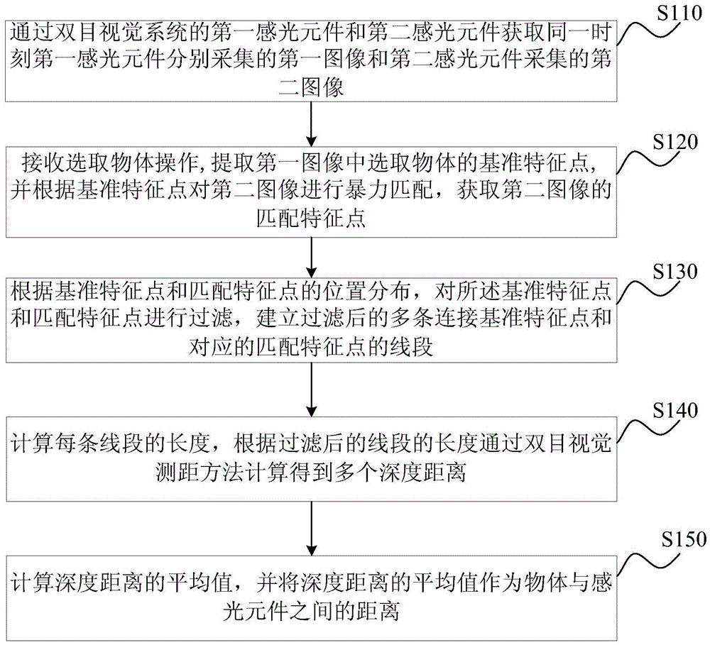
[0025] figure 1 It is a flow chart of the binocular vision-based ranging method provided in the first embodiment of the present invention. This embodiment can be applied to a small UAV to measure the distance between a small UAV and an object. The method can be based on binocular It can be implemented by a visual ranging device, which can be realized by software / hardware and integrated in a small UAV ranging device.

[0026] Described method specifically comprises as follows:

[0027] S110. Obtain the first image respectively collected by the first photosensitive element and the second image collected by the second photosensitive element at the same moment through the first photosensitive element and the second photosensitive element of the binocular vision system.

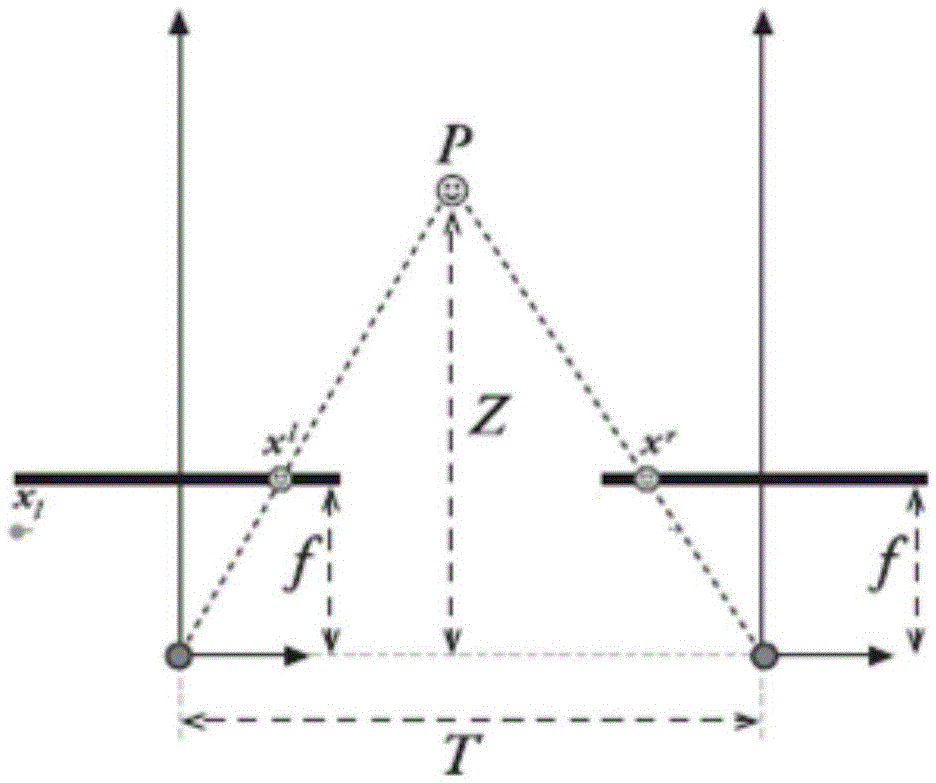
[0028] figure 2 It is a schematic diagram of the principle of binocular distance measurement in the distance measurement method based on binocular vision provided by the first embodiment of the present inventio...

Embodiment 2

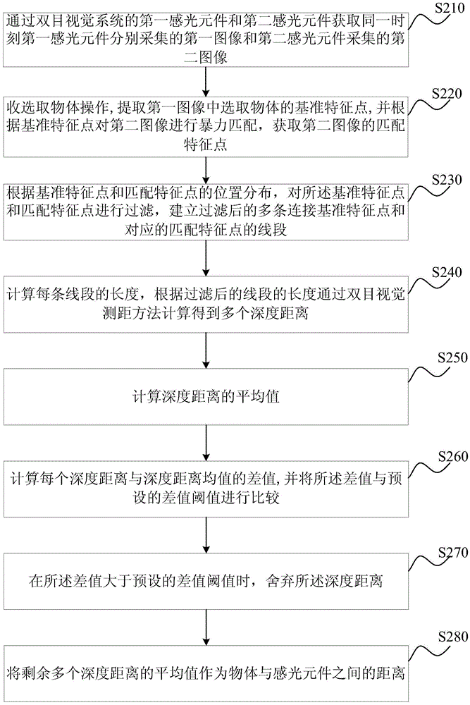
[0044] image 3 It is a schematic flowchart of a binocular vision-based ranging method provided in the second embodiment of the present invention. This embodiment is optimized on the basis of the above-mentioned embodiments. In this embodiment, after calculating the average value of the depth distance, the following steps are added: calculate the difference between each depth distance and the average value of the depth distance, and convert the difference Compared with the preset difference threshold, when the difference is greater than the preset difference threshold, the depth distance is discarded; and the average value of multiple depth distances is used as the distance between the object and the photosensitive element, specifically The optimization is: take the average value of the remaining multiple depth distances as the distance between the object and the photosensitive element.

[0045] Correspondingly, the method in this embodiment specifically includes:

[0046] S...

Embodiment 3

[0061] Figure 4 It is a schematic flowchart of a binocular vision-based ranging method provided by the third embodiment of the present invention. This embodiment is optimized on the basis of the above embodiments. In this embodiment, after the average value of the depth distance is calculated, the following steps are added before the average value of the depth distance is used as the distance between the object and the photosensitive element : respectively calculate the average value of the depth distance corresponding to each preset moment before and after the same moment; the average value of the depth distance is used as the distance between the object and the photosensitive element, and the specific optimization is: calculate the corresponding The average value of the average value of the depth distance is used as the distance between the object and the photosensitive element.

[0062] Correspondingly, the method in this embodiment specifically includes:

[0063] S310. ...


PUM


Abstract

The invention discloses a distance measurement method and a device based on binocular vision. The method comprises steps of acquiring a first image acquired by a first light sensing element and a second image acquired by a second light sensing element at the same time; receiving a selected object, extracting a standard characteristic point of the selected object in the first image, carrying out violence matching on the second image according to the standard characteristic point and acquiring a matching characteristic point of the second image; according to position distribution of the standard characteristic point and the matching characteristic point, filtering the standard characteristic point and the matching characteristic point and establishing multiple line segments for connecting the standard characteristic point and the corresponding matching characteristic point after filtering; calculating length of each of the line segments and calculating multiple depth distances by means of binocular vision distance measurement according to the lengths of the filtered line segments; and calculating an average value of the depth distances and using the average value of the depth distances as a distance between the object and the sensing elements. Thus, while the distance between the object and a camera can be quickly obtained, calculation precision is ensured.

Description

technical field [0001] The invention relates to the technical field of visual ranging, in particular to a binocular vision-based ranging method and device. Background technique [0002] Due to the uncertainty of the flight environment, small UAVs cannot use the pre-planned path, and can only fly by autonomous obstacle avoidance. How to measure the distance between obstacles and small drones is an important factor that determines whether small drones can autonomously avoid obstacles. [0003] At present, there are mainly two ways to measure the distance between obstacles and small UAVs. First, measure the distance of obstacles through laser rangefinders or acoustic wave detectors equipped on small UAVs. Although this method can Accurately measure the distance between obstacles and small drones, but the laser rangefinder or acoustic detector is heavy, which affects the flight performance of small drones. Second, using visual distance measurement, the distance between the obs...

Claims


Application Information

Patent Timeline
IPC IPC(8): G01B11/02
CPCG01B11/026
Inventor 杨建军蒲庆卢杰刚吴德鑫胡益铭谢帅宁
Owner ZEROTECH (SHENZHEN) INTELLIGENCE ROBOT CO LTD
Why Eureka
Try Eureka