Hydraulic oscillation drag reduction drilling tool simulation experimental device

A technology for simulating experimental devices and hydraulic oscillators, which is applied in the testing of measuring devices, instruments, and mechanical components, can solve problems such as time-consuming and affecting the drilling efficiency of well sections, expand the scope of research, simplify experimental costs, and reduce effect of influence

Inactive Publication Date: 2016-06-01
CHINA UNIV OF GEOSCIENCES (BEIJING)
View PDF5 Cites 0 Cited by
  • Summary
  • Abstract
  • Description
  • Claims
  • Application Information

AI Technical Summary

Problems solved by technology

[0003] Although the research on hydraulic oscillators has gradually matured, most of the experimental research uses finished products for on-site research, and the research content is limited to the overall drilling efficiency. Although this research method is feasible, it takes a long time, especially If there is a problem with the tool during the research process, it will seriously affect the drilling efficiency of the well section

Method used


Image

  • Hydraulic oscillation drag reduction drilling tool simulation experimental device
  • Hydraulic oscillation drag reduction drilling tool simulation experimental device

Examples


Embodiment Construction

[0025] Below in conjunction with embodiment and its Figure 1-2 The present invention is described in further detail. The following examples are only descriptive, not restrictive, and cannot limit the protection scope of the present invention.

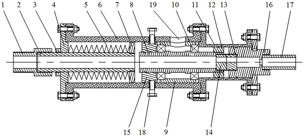
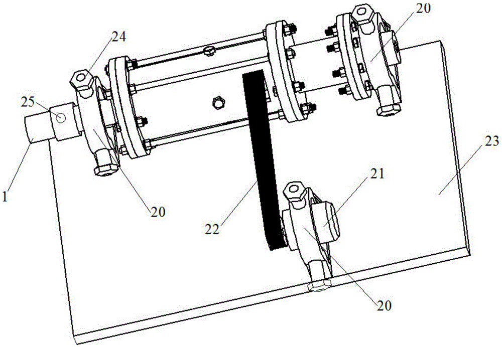
[0026] Such as figure 1 with figure 2 as shown, figure 1 It is a structural schematic diagram of the hydraulic oscillation drag reduction drilling tool simulation experiment device of the present invention, figure 2 It is a structural schematic diagram of the hydraulic oscillator of the hydraulic oscillation drag reduction drilling tool simulation experiment device of the present invention.

[0027] A hydraulic oscillating drag reduction drilling tool simulation experiment device, including a hydraulic oscillator, the hydraulic oscillator includes an outer cylinder, a rotating shaft 8, a support seat 16 and a vibration shaft 2, the rotating shaft 8 is covered with a supporting bearing 10, and the rotating shaft 8 passes through th...


PUM


Abstract

The invention discloses a hydraulic oscillation drag reduction drilling tool simulation experimental device. The hydraulic oscillation drag reduction drilling tool simulation experimental device comprises a hydraulic oscillator; the hydraulic oscillator comprises an outer cylinder, a rotating shaft, a support seat and a vibration shaft; the vibration shaft is sleeved with a support bearing; the vibration shaft is arranged in the cavity of the outer cylinder through the support bearing; the support seat is fixedly connected with one end of the outer cylinder; the vibration shaft is arranged at the other end of the outer cylinder; one end of the vibration shaft extends into the outer cylinder, and the other end of the vibration shaft is located outside the outer cylinder; the outer edge of the one end of the vibration shaft which extends into the outer barrel extends outwards along a radial direction to form a support surface; the end surface of one end of the outer cylinder is connected with a flange, wherein the one end of the outer cylinder is provided with the vibration shaft; a spring is arranged between the flange and the support surface in a filling manner; a portion of the vibration shaft, which is located outside the outer cylinder, is sleeved with a pre-compression nut; one end of the rotating shaft, which faces the support seat, is fixedly connected with a main valve having an eccentric hole, and correspondingly, the support seat is provided with an auxiliary valve having the same eccentric hole as the main valve; and the main valve and the auxiliary valve have end surfaces which are attached to each other. With the hydraulic oscillation drag reduction drilling tool simulation experimental device adopted, a simulation test of an oscillation drag reduction drilling tool can be carried out.

Description

technical field [0001] The invention relates to a simulation experiment device, in particular to a simulation experiment device of a hydraulic oscillation drag reduction drilling tool with small flow rate and small inner diameter. Background technique [0002] In the prior art, in the wellbore with large curvature or long horizontal well section, the inability to effectively transmit the weight on bit is an important factor affecting the rate of penetration. In this well section, the borehole wall is subjected to greater pressure from the drill string, and the friction between the drill string and the borehole wall increases accordingly. Therefore, during the drilling process, the underpinning phenomenon of the drill string is serious, resulting in the inability to apply the ideal WOB, which seriously affects the drilling speed. When the friction between the drill string and the borehole wall is large enough, it is easy to cause the drill string to twist and deform and indu...

Claims


Application Information

Patent Timeline
Patent Type & Authority Applications(China)
IPC IPC(8): G01M13/00
CPCG01M13/00
Inventor 王瑜邹俊夏柏如刘宝林王志乔周琴刘彬李学飞张尊王绪强
Owner CHINA UNIV OF GEOSCIENCES (BEIJING)
Why Eureka
Try Eureka