

Transformer temperature control device and method
A technology for temperature control devices and transformers, applied in temperature control, non-electric variable control, control/regulation systems, etc., can solve the problems of transformers being easily damaged by overheating, and achieve the effect of reducing economic losses and recovering economic losses
- Summary
- Abstract
- Description
- Claims
- Application Information
AI Technical Summary
Problems solved by technology
Method used
Image

Examples
Embodiment Construction
[0022] The specific implementation manners of the present invention will be described in detail below in conjunction with the accompanying drawings.
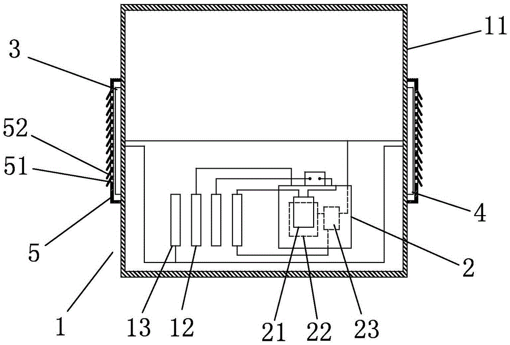
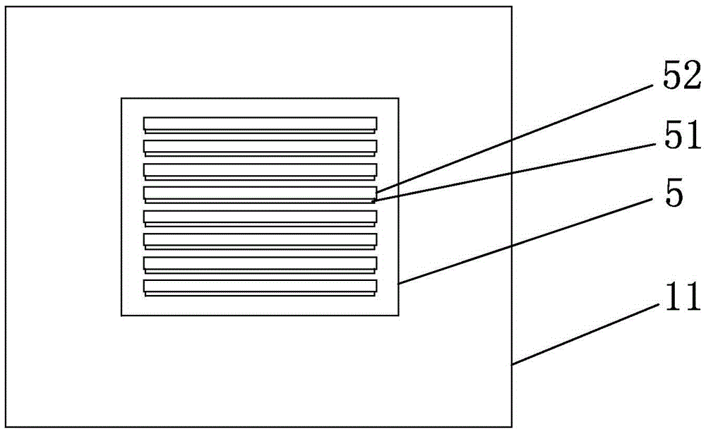
[0023] Such as figure 1 and image 3 As shown, a transformer temperature control device is arranged on a transformer 1. The transformer has a casing 11 and a low-voltage side three-phase pile head 12 and a zero-phase pile head 13 arranged in the casing 11, and a low-voltage side three-phase pile head 12 Including A-phase pile head, B-phase pile head and C-phase pile head, the voltage between A-phase pile head, B-phase pile head and C-phase pile head and zero-phase pile head 13 is 220V, and the transformer temperature control device includes setting The temperature controller 2 inside the transformer housing 11 and the air inlet fan 3 and the air outlet fan 4 arranged on the transformer housing 11, the fan installation directions of the air inlet fan 3 and the air outlet fan 4 are opposite, and the air inlet fan 3 starts At the...
PUM
 Abstract
Description
Claims
Application Information