Motor capable of realizing stator closed and rotor open ventilation mode by adopting axial-flow ventilation

A ventilation method and motor technology, which is applied to electric components, cooling/ventilation devices, magnetic circuit rotating parts, etc., can solve the problems of excessive heating of the rotor, burning the motor, and tedious installation work, achieving high power density, simplified structure, Compact form factor

Active Publication Date: 2016-06-01
滁州精镁装备模具制造有限公司
View PDF6 Cites 22 Cited by
  • Summary
  • Abstract
  • Description
  • Claims
  • Application Information

AI Technical Summary

Problems solved by technology

[0011] At present, open forced ventilation traction motors are commonly used in high-speed trains and locomotives, because vehicles require high motor power, and the existing open self-ventilated motors are too large to accommodate the bogie space; open forced ventilation traction motors Independent fans and air ducts are required, and they are arranged under the carriage. The installation work is very cumbersome, and it is a very troublesome task for the entire vehicle factory.
[0012] 4. The rotor of the three-phase asynchronous motor generates a lot of heat. Usually, the operating temperature of the rotor is 50 to 100 degrees higher than that of the stator. The heat of the rotor is easily transmitted to the bearing through the shaft. The high operating temperature of the bearing will reduce the performance of the grease and reduce the life of the bearing; The excessive expansion of the inner ring of the bearing may cause the working clearance of the bearing to disappear, the bearing will be stuck and the motor will be burned

Method used


Image

  • Motor capable of realizing stator closed and rotor open ventilation mode by adopting axial-flow ventilation
  • Motor capable of realizing stator closed and rotor open ventilation mode by adopting axial-flow ventilation
  • Motor capable of realizing stator closed and rotor open ventilation mode by adopting axial-flow ventilation

Examples


Embodiment Construction

[0098] Referring now to the drawings, wherein like reference numerals refer to the same or corresponding parts throughout the several views;

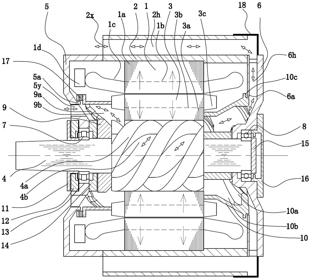
[0099] attached figure 1 It is an axial cross-sectional view of the first embodiment of the present invention. figure 1 The implementation of the first embodiment will be described:

[0100] The feature of the first embodiment is that the stator air duct 2h of the motor casing 2 is located at the four corners of the maximum width and height outside the motor body, does not occupy the motor circumference, and reserves the maximum diameter for the stator and rotor, so that the motor has a higher size. power density; two air vents are located on the front cover and on the circumference of the casing on the side of the drive end, suitable for electric motors used to drive subway vehicles;

[0101] Step 1. The stator 1 includes a stator core 1a and a stator winding 1b. The inner circumference of the stator core 1a is evenly distributed wit...


PUM


Abstract

The invention discloses a motor capable of realizing a stator closed and rotor open ventilation mode by adopting axial-flow ventilation. An adopted shaft is provided with an external circumferential spiral groove, and the spiral groove matches with axial-flow fans with two clingy ends and the same spiral directions to form an axial-flow combined ventilation apparatus; the apparatus is arranged in a rotor and at two ends of the rotor, and the extra axial space of the motor is not occupied, so that the motor is compact in structure; due to different steering directions, airflow directions are also different but the motor can be cooled; in combination with labyrinth seal, a combined cooling mode of stator closed ventilation cooling and rotor open ventilation cooling of the motor is realized, and the combined cooling mode enables the insulation reliability of a stator and the heat dissipation capability of a rotor to be both ensured and improves the motor efficiency; a stator cooling air duct consists of vent holes (2x), a stator air duct (2h) and an air duct section (6h); a rotor cooling air duct consists of vent holes (5y), gaps (9b), a spiral groove (4b) and gaps (10b); the two cooling air ducts are connected in series; and the spiral combined apparatus provides air pressures for the cooling air ducts.

Description

technical field [0001] The present invention relates to a totally enclosed self-ventilated electric motor for industrial applications and for driving railway vehicles. Background technique [0002] The heat generated by the stator and the rotor of the three-phase asynchronous motor accounts for about half, and the heat generated by the stator of the industrial motor is slightly higher than that of the rotor. The traction motor used for railway vehicles has a large workload and a large slip rate of the rotor, and the heat generated by the rotor will reach the overall heat generation. More than half of the calories; [0003] Railway vehicles run on two steel rails with a standard gauge of 1435 mm. The power module consisting of traction motors, couplings, and gearboxes is placed in this fixed space. At the same time, a certain amount of daily maintenance space needs to be reserved for the operators. At the same time, rail transit works in an open-air environment and is subjec...

Claims


Application Information

Patent Timeline
Patent Type & Authority Applications(China)
IPC IPC(8): H02K9/06H02K1/32H02K5/20H02K9/08
CPCH02K1/32H02K5/20H02K9/06H02K9/08
Inventor 冯亮
Owner 滁州精镁装备模具制造有限公司
Why Eureka
Try Eureka