valve

A technology for controlling valves and valve components, which is applied in the field of valves and can solve problems such as wear and noise

Active Publication Date: 2019-08-09
VTESCO TECH GMBH
View PDF6 Cites 0 Cited by
  • Summary
  • Abstract
  • Description
  • Claims
  • Application Information

AI Technical Summary

Problems solved by technology

Noise and mechanical wear can occur due to the mechanical pulses of the switching magnets in conventional valves

Method used


Image

  • valve
  • valve
  • valve

Examples


Embodiment Construction

[0014] In the exemplary embodiments and figures, identical, similar or identically acting elements may in each case be identified by the same reference numerals. The illustrated proportions of these elements and of these elements to each other should not be considered true to scale; rather, individual elements such as layers, components, structural elements and regions may be shown exaggerated in scale for better visual presentation and / or understand better.

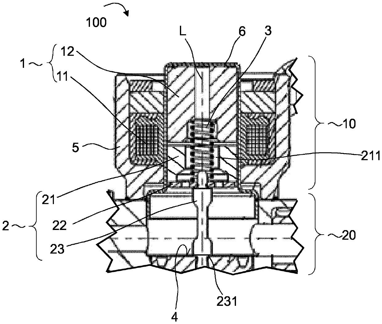
[0015] figure 1 Details of a valve 100 are shown, which are notably configured as solenoid valves and may be, for example, pressure control valves for controlling the pressure of a fluid in a pressure circuit. For example, valve 100 may be used in an accumulator injection system for an internal combustion engine.

[0016] The valve 100 has a control unit 10 and a valve element 20 . The valve element 20 , shown only in detail, can have, for example, a valve needle or a valve flap, which can be controlled by a control ...


PUM


Abstract

The present invention relates to a valve, which comprises a control unit for controlling the valve element (20) (10). The control unit (10) having an electromagnet (1) and a armature set (2); the solenoid (1) having a coil (11) and a core (12), the armature set (2) having a magnetic armature capable of moving through the electromagnet (1) (21), an intermediate element (22) and a control pin for controlling the valve element (20) (23); the control pin (23) is connected to the magnetic armature (21) by the intermediate element (22), and can be moved with the magnetic armature (21). The intermediate element (22) is elastic and the control pin (23) is elastically coupled to the magnetic armature (21).

Description

technical field [0001] The invention describes a valve. In particular, the valve may be a pressure control valve for controlling the fluid pressure in a pressure circuit and may be used, for example, in an accumulator injection system for an internal combustion engine of a motor vehicle. Background technique [0002] Known valves of this type can have switching magnets which bring about the opening and / or closing of the valve. Noise and mechanical wear can occur due to the mechanical pulses of the switching magnets in conventional valves. To avoid noise, for example, the current aim is to reduce the mass of moving parts or to reduce magnetic forces by adapting the electrical actuation. For example, use hardened materials to avoid abrasion. Contents of the invention [0003] In the following, a valve with reduced noise development and / or reduced wear will be described. [0004] This object is achieved by the subject matter according to the independent claims. Advantage...

Claims


Application Information

Patent Timeline
Patent Type & Authority Patents(China)
IPC IPC(8): F02M63/00
CPCF02M63/0015F02M63/0022F02M63/0014F02M2200/306F16K31/0675
Inventor M.布利克R.韦伯B.韦利施
Owner VTESCO TECH GMBH
Why Eureka
Try Eureka