
Concrete mixing bunker as well as concrete wet-process injection system and method based on concrete mixing bunker

A technology of wet spraying and concrete, which is applied in the direction of chemical instruments and methods, mixing operation control, mixing operation control device, etc. It can solve the problems of high construction cost, large dust on the construction site, large strength dispersion, etc., and achieve raw material utilization rate High, high sampling intensity, high reaction efficiency

Inactive Publication Date: 2014-12-31
陕西金石混凝土科技发展有限公司
View PDF5 Cites 0 Cited by
  • Summary
  • Abstract
  • Description
  • Claims
  • Application Information

AI Technical Summary

Problems solved by technology

[0002] Dry shotcrete is directly mixed with concrete and dry materials in the shotcrete without adding water, so the construction site is dusty, which seriously endangers the health of workers
Since water is added at the nozzle, not only the water-cement ratio of shotcrete is difficult to control, but also the cement hydration is not sufficient, resulting in large dispersion of shotcrete strength, large rebound, and serious waste
[0003] For tidal shotcrete, since the dry powder accelerator is manually added into the dry spray machine together with the mixture at the feed port of the dry spray machine, the dry powder accelerator cannot be added accurately
Moreover, when the amount of water added to the mixed tidal material is excessive, the mixture will condense and harden in the dry spraying machine and block the dry spraying machine or pipeline.
Compared with dry spraying, there are also fatal problems that are difficult to solve, such as large spray rebound and large intensity dispersion
[0004] The existing wet spraying method is difficult to implement and popularize, mainly because on the one hand, the spraying equipment is expensive, and on the other hand, the construction cost is too high. If the wet-mixed concrete material is not used in time, not only the amount of accelerator will be increased, but also it is difficult to ensure the strength of the sprayed concrete , a large waste of raw materials
[0005] Patent ZL200810130718.7 discloses a concrete dry material wet spraying machine. This model simply adds water to the delivery pipeline to achieve the effect of changing the dry material to wet material, without considering the change of the state of the concrete material from dry material to wet material. It will inevitably lead to concrete pipe blockage and discharge pulse, which will seriously affect the construction of sprayed concrete, and even lead to the failure of the wet spraying process.

Method used


Image

  • Concrete mixing bunker as well as concrete wet-process injection system and method based on concrete mixing bunker
  • Concrete mixing bunker as well as concrete wet-process injection system and method based on concrete mixing bunker
  • Concrete mixing bunker as well as concrete wet-process injection system and method based on concrete mixing bunker

Examples


Embodiment 1

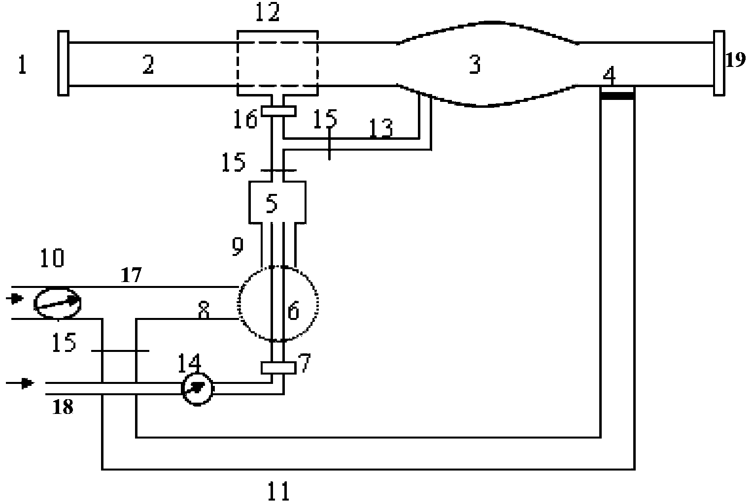
[0039] Step 1, at first mix the aggregates of the concrete evenly in the mixer according to the gray-water ratio of 1:0.15~0.2, transport them to the construction site with a tank truck or a dump truck, and add it to the injection machine of the present invention manually or mechanically in the hopper;

[0040] Step 2: Use compressed air to transport the mixture to the concrete mixing chamber. The mixture passes through the material mixing chamber (hereinafter referred to as the mixing chamber) twice and then adds water to form a plastic mixture in the mixing chamber. Here, the water passes through first. The air-water mixer is atomized and then added to the water adding ring and the mixing chamber respectively. The amount of water added is determined by the concrete mix ratio and controlled by flow meters and valves;

[0041] Step 3: The plastic mixture is transported to the nozzle under the action of the compressed air in the delivery pipe and the auxiliary compressed air, a...

Embodiment 2

[0043] Step 1, at first mix the aggregates of the concrete evenly in the mixer according to the gray-water ratio of 1:0.15~0.2, transport them to the construction site with a tank truck or a dump truck, and add it to the injection machine of the present invention manually or mechanically in the hopper;

[0044] Step 2: Use compressed air to transport the mixture to the concrete mixing chamber. The mixing chamber has been removed from the mixing chamber here. The water passes through the air-water mixer and then enters the water adding ring and then enters the conveying pipeline, and is mixed with the liquid at the nozzle. Spray out after the accelerator works.

Embodiment 1

[0046] Step 1, mix the concrete aggregate evenly, and add the mixture into the hopper of the dry spraying machine by manual feeding, and manually sprinkle the powdered quick-setting agent in the hopper after starting the spraying machine;

[0047] Step 2: The mixing material and quick-setting agent are transported to the nozzle under the action of compressed air, and are sprayed out quickly by the action of the water added to the nozzle.


PUM

PropertyMeasurementUnit
sizeaaaaaaaaaa

Abstract

The invention discloses a concrete mixing bunker as well as a concrete wet-process injection system and method based on the concrete mixing bunker. The concrete mixing bunker comprises a feeding pipe, wherein the feeding pipe is provided with a blending bunker, a water adding ring is connected to the feeding pipe and the front part of the blending bunker and connected with a water atomization chamber through a pipeline, and an inlet of the water atomization chamber is connected with a spherical nozzle; an air inlet of the spherical nozzle is connected with an air pipe, and a water inlet is connected with a water pipe; and a branch divided from an air pipe is connected to the feeding pipe behind the blending bunker. The injection system provided by the invention is additionally provided with the concrete mixing bunker for blending a moist concrete material into wet plastic material; and due to the adoption of the design of the mixing bunker, not only is a dry material wet spraying process realized, but also the problems of pipe blockage by concrete and discharge pulse can be avoided.

Description

technical field [0001] The invention belongs to the technical field of concrete spraying machines, and relates to the design of a concrete mixing bin, in particular to a concrete mixing bin and a concrete wet spraying system and method based thereon. Background technique [0002] Dry shotcrete is directly added to concrete and mixed dry materials in the shotcrete without adding water, so the construction site is dusty, which seriously endangers the health of workers. Since the water is added at the nozzle, not only the water-cement ratio of shotcrete is difficult to control, but also the cement hydration is not sufficient, resulting in large dispersion of shotcrete strength, large rebound, and serious waste. [0003] In tidal shotcrete, since the dry powder quick-setting agent is manually added into the dry spraying machine at the feed port of the dry spraying machine together with the mixture, the dry powder quick-setting agent cannot be added accurately. Moreover, when th...

Claims


Application Information

Patent Timeline
Patent Type & Authority Patents(China)
IPC IPC(8): B28C7/04E04G21/02
Inventor 王宏军胡池芳
Owner 陕西金石混凝土科技发展有限公司
Learn More