
Method for manufacturing flat tubes

A manufacturing method and a technology of flat tubes, applied in the field of solar heat collectors, can solve the problems of large heat collectors, unsightly appearance, and low absorption efficiency, so as to simplify the sealing process, improve light-to-heat conversion efficiency, and reduce labor force Effect

Inactive Publication Date: 2016-06-08
徐晓冰
View PDF7 Cites 7 Cited by
  • Summary
  • Abstract
  • Description
  • Claims
  • Application Information

AI Technical Summary

Problems solved by technology

[0003] However, according to the applicant's understanding, the existing absorbing surface of the heat collecting tube is difficult to fully absorb light, and its absorption efficiency is low, and the heat collector formed by the heat collecting tube is large in size, requires a large footprint, and has an unattractive appearance.

Method used


Image

  • Method for manufacturing flat tubes
  • Method for manufacturing flat tubes

Examples


Embodiment 1

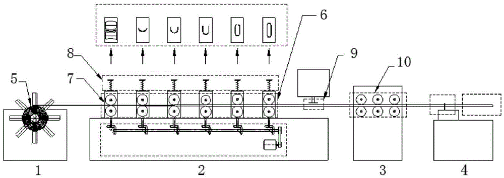
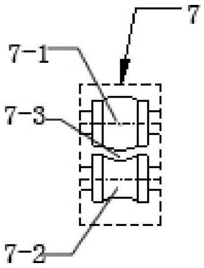
[0015] A kind of flat tube manufacturing method provided by this embodiment, such as figure 1 and figure 2 As shown, it includes the rough pressing forming stage, fine pressing size stage, closing stage and welding sealing stage. Both the rough pressing forming stage and the fine pressing size stage are rolled by the continuous mold of the platen machine 2, and the continuous extension mold group is installed on the platen machine 2. 6. There are at least three roller groups 7 in the 6 groups of continuous extension molds, and each roller group 7 rotates synchronously with the linkage device on the platen machine. The synchronous linkage device includes a linkage shaft. The shaft is driven by a motor to rotate the rotating shaft. The roller group 7 includes an upper roller 7-1 and a lower roller 7-2 which are set up and down oppositely. The upper roller 7-1 has a conical boss extending radially, and the lower roller 7-2 has a radially inward conical groove adapted to the upp...


PUM


Abstract

The invention relates to a method for manufacturing flat tubes. The method includes a coarse pressing forming phase, a dimensional fine pressing phase, a shell nosing phase and a welding sealing phase. Rolling is carried out by progressive dies of a plate pressing machine in the coarse pressing forming phase and the dimensional fine pressing phase, progressive drawing die sets are mounted on the plate pressing machine, at least three roller groups are arranged in each progressive drawing die set and synchronously rotate on the plate pressing machine in a linkage manner, each roller group comprises an upper roller and a lower roller which are oppositely arranged in the up-down direction, the upper rollers are provided with conical bosses which outwardly extend, radially inward conical grooves which are matched with the upper rollers are formed in the lower rollers, roller gaps for pressing and forming metal sheets are reserved between the conical bosses and the conical grooves, and pressures which are applied by the upper rollers and the lower rollers on the central metal sheets are 0.5-5 KG. The method has the advantages that the plate pressing machine coarsely presses and finely presses the metal sheets, then the metal sheets are formed by the aid of shell nosing working procedures and high-frequency welding, and accordingly the flat tubes can be quickly formed.

Description

technical field [0001] The invention relates to a heat collecting tube in the field of solar heat collectors, in particular to a method for manufacturing a flat tube. Background technique [0002] Most of the existing heat collectors use cylindrical heat collecting tubes or spiral heat collecting tubes, such as the Chinese invention patent "New Heat Collecting Tube" with application number 201210426411.8, the heat collecting tubes include glass inner tubes and glass outer tubes, glass inner tubes and glass There is a vacuum layer between the outer tubes, and the glass inner tube adopts a spiral tube. Or if the PCT with the application number 201380040165.5 introduces the domestic invention patent "solar heat collector tube", the central metal tube and the central tube socketed on it are used to absorb the thermal expansion difference between the central metal tube and the glass tube through the absorption device, and the metal tube and glass tubes are cylindrical tubes. ...

Claims


Application Information

Patent Timeline
Patent Type & Authority Applications(China)
IPC IPC(8): B21C37/08B21D5/12
CPCB21C37/08B21D5/12
Inventor 徐晓冰陈卫宁
Owner 徐晓冰
Learn More