Clamping device for precisely machining inner surface of conformal optical cowling

A clamping device and precision machining technology, which is applied in the direction of clamping device, positioning device, metal processing equipment, etc., can solve the problems that it is difficult to completely fix the fairing, the total deformation is unpredictable, and the processing accuracy is difficult to guarantee. The effect of high precision, improving processing accuracy, ensuring processing accuracy and processing efficiency

Active Publication Date: 2016-06-08
HARBIN INST OF TECH
View PDF7 Cites 10 Cited by
  • Summary
  • Abstract
  • Description
  • Claims
  • Application Information

AI Technical Summary

Problems solved by technology

[0004] The present invention solves the problem of the precision machining of the existing shape-conforming optical dome inner surface. The clamping device is an annular structure in which the joint surface of the fixture is distributed in steps. Since the outer surface of the dome and the clamping device inevitably have a certain surface shape error

Method used


Image

  • Clamping device for precisely machining inner surface of conformal optical cowling
  • Clamping device for precisely machining inner surface of conformal optical cowling
  • Clamping device for precisely machining inner surface of conformal optical cowling

Examples


specific Embodiment approach 1

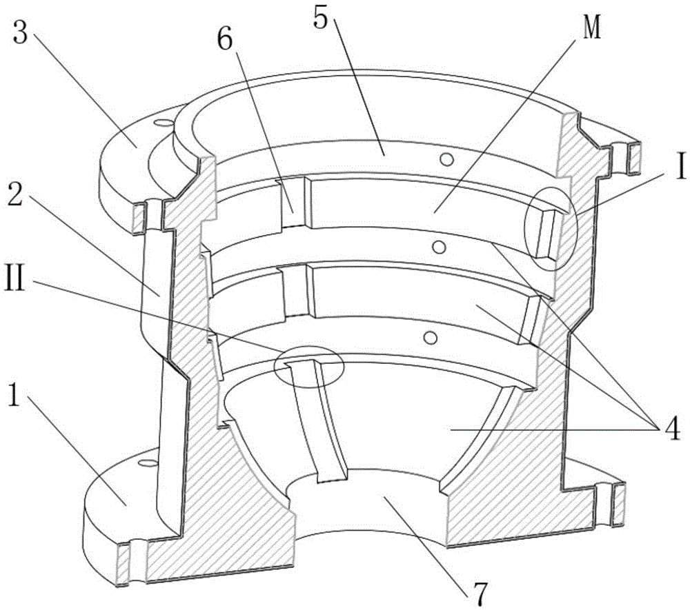
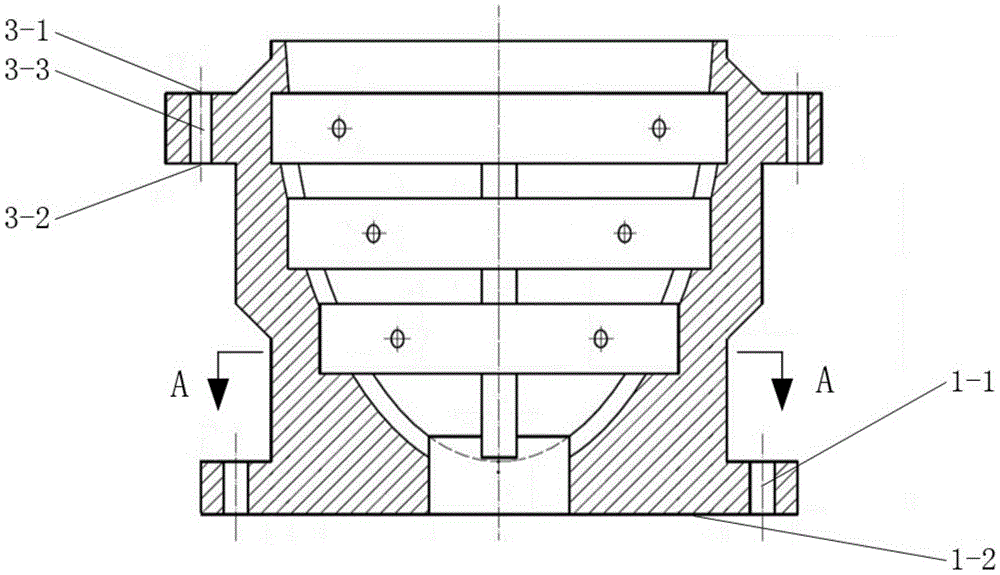
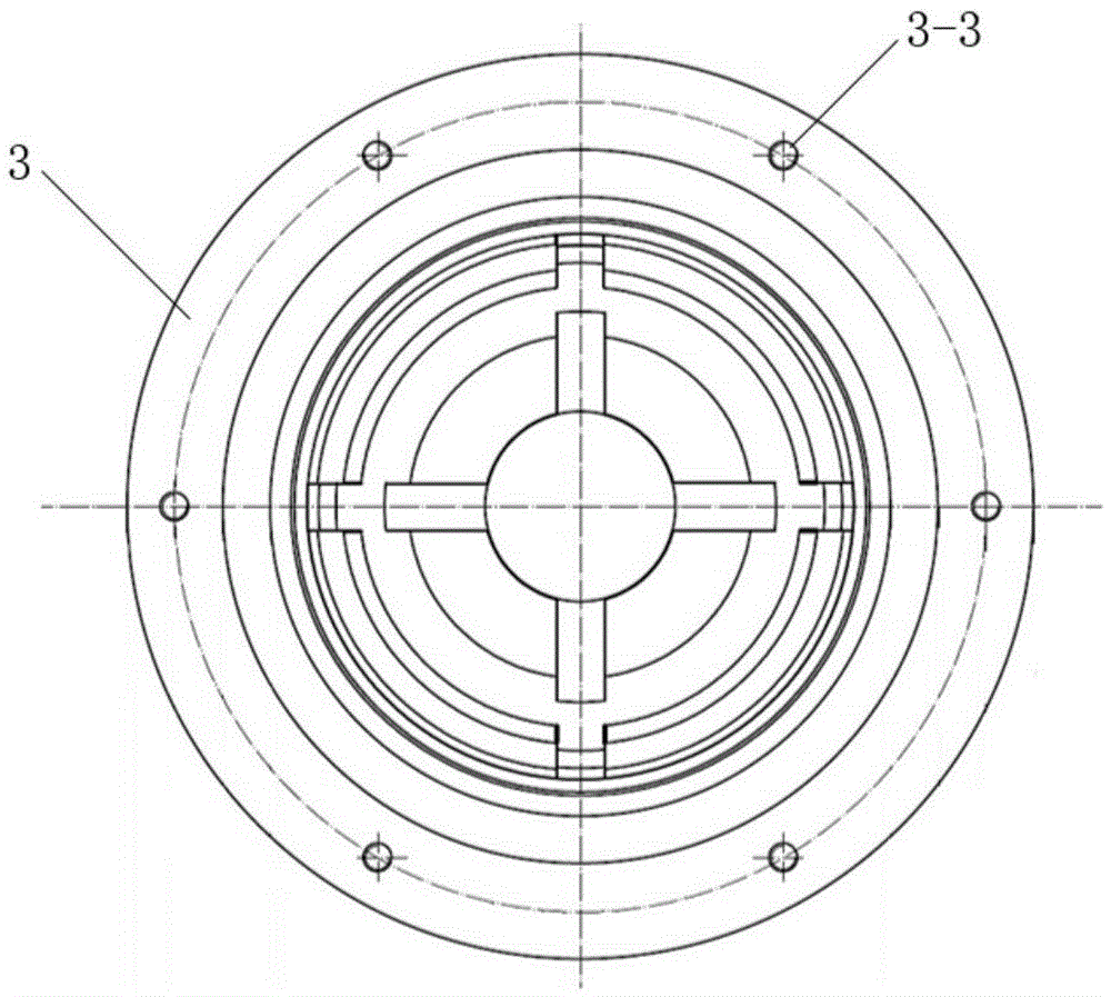
[0018] Specific implementation mode one: combine Figure 1 to Figure 6 Describe this embodiment, this embodiment includes a base body 2, the upper end of the base body 2 is provided with a flange 3, the lower end of the base body 2 is provided with a base 1, the inner cavity of the base body 2 is a curved surface cavity M, and the curved surface cavity The cross-section of M is a variable section that gradually decreases from top to bottom. Several annular positioning bosses 4 are arranged on the inner wall of the curved surface cavity M. Consistent, there are transverse grooves 5 between adjacent two annular positioning bosses 4, longitudinal grooves 6 are provided on several annular positioning bosses 4, and the center of the bottom of the base body 2 is provided with a curved inner cavity M Interlinked through holes 7 avoid positioning errors caused by size errors and surface shape errors at the top of the fairing, and the diameter and height of the through holes 7 determin...

specific Embodiment approach 2

[0019] Specific implementation mode two: combination Figure 5 To describe this embodiment, the height h of the annular positioning boss 4 in this embodiment is 20 mm to 100 mm, and the thickness s of the annular positioning boss 4 is 3 mm to 50 mm. The size of the annular positioning boss 4 is an important factor affecting the total deformation of the fairing and the local stress concentration, and should be designed through theoretical analysis and simulation calculation. Other components and connections are the same as those in the first embodiment.

specific Embodiment approach 3

[0020] Specific implementation mode three: combination Figure 5 To describe this embodiment, the height h of the annular positioning boss 4 in this embodiment is 50mm, and the thickness s of the annular positioning boss 4 is 10mm. The size of the annular positioning boss 4 is an important factor affecting the total deformation of the fairing and the local stress concentration, and should be designed through theoretical analysis and simulation calculation. Other components and connections are the same as those in the second embodiment.


PUM

PropertyMeasurementUnit
Heightaaaaaaaaaa
Thicknessaaaaaaaaaa
Heightaaaaaaaaaa

Abstract

The invention relates to a clamping device for precisely machining an inner surface of a conformal optical cowling, which relates to a machining clamping device, and aims at solving the problem that unpredictable total deformation can be produced because a joint surface of the existing clamping device for precisely machining the inner surface of the conformal optical cowling is in a local contact and even in a point contact, the cowling is difficult to completely fix and the machining precision is difficult to guarantee. The upper end of a basal body is provided with a flange, the lower end of the basal body is provided with a base, an inner cavity of the basal body is a curved inner cavity, the cross section of the curved inner cavity is a variable cross section which is gradually narrowed from top to bottom, a plurality of annular positioning bosses are arranged on the inner wall of the curved inner cavity, the curved radian of each annular positioning boss is consistent with that of the outer surface of the cowling, a transverse groove is formed between two adjacent annular positioning bosses, longitudinal grooves are formed in the plurality of annular positioning bosses, and a through hole which is communicated with the curved inner cavity is formed in the center of the bottom of the basal body. The clamping device is used for precisely machining the inner surface of the conformal optical cowling.

Description

technical field [0001] The invention relates to a clamping device for mechanical processing, in particular to a clamping device for precise machining of the inner surface of a conformal optical dome. Background technique [0002] At present, the requirements for the speed of aircraft are getting higher and higher. In order to adapt to the development of high-speed aircraft and balance the aerodynamic requirements of the aircraft, the contradiction between stealth and optical performance, conformal optical components have emerged as the times require, namely: to improve the aerodynamics of the system The optical window smoothly adapts to the external shape of the system platform for the purpose of chemical performance. The primary key element in the application of conformal optical components is the fairing of the aircraft. Compared with the traditional hemispherical fairing, the conformal optical fairing can significantly reduce the flight resistance of the aircraft, improve...

Claims


Application Information

Patent Timeline
IPC IPC(8): B23Q3/00
CPCB23Q3/00B23Q2703/10
Inventor 郭兵张春雨王金虎顾兴士赵清亮孙金霞陈洪许
Owner HARBIN INST OF TECH
Why Eureka
Try Eureka