
Earth-retaining wall structure with steel tube reinforcing ribs and construction method for earth-retaining wall structure

A construction method and retaining wall technology, which is applied in the direction of basic structure engineering, underwater structures, artificial islands, etc., can solve the problems of long construction time, low efficiency ratio, poor economy and reliability, etc., so as to save construction period and high Cost-effective, structurally reliable results

Active Publication Date: 2016-06-08
CHINA CONSTR EIGHT ENG DIV CORP LTD
View PDF4 Cites 4 Cited by
  • Summary
  • Abstract
  • Description
  • Claims
  • Application Information

AI Technical Summary

Problems solved by technology

[0004] The purpose of the present invention is to overcome the defects of the prior art, provide a steel pipe bone rib retaining wall structure and its construction method, and solve the construction time in the existing brick gravity retaining wall using structural columns and waist beams Long, low efficiency ratio, poor economy and reliability

Method used


Image

  • Earth-retaining wall structure with steel tube reinforcing ribs and construction method for earth-retaining wall structure
  • Earth-retaining wall structure with steel tube reinforcing ribs and construction method for earth-retaining wall structure
  • Earth-retaining wall structure with steel tube reinforcing ribs and construction method for earth-retaining wall structure

Examples


Embodiment Construction

[0036] The present invention will be further described below in conjunction with the accompanying drawings and specific embodiments.

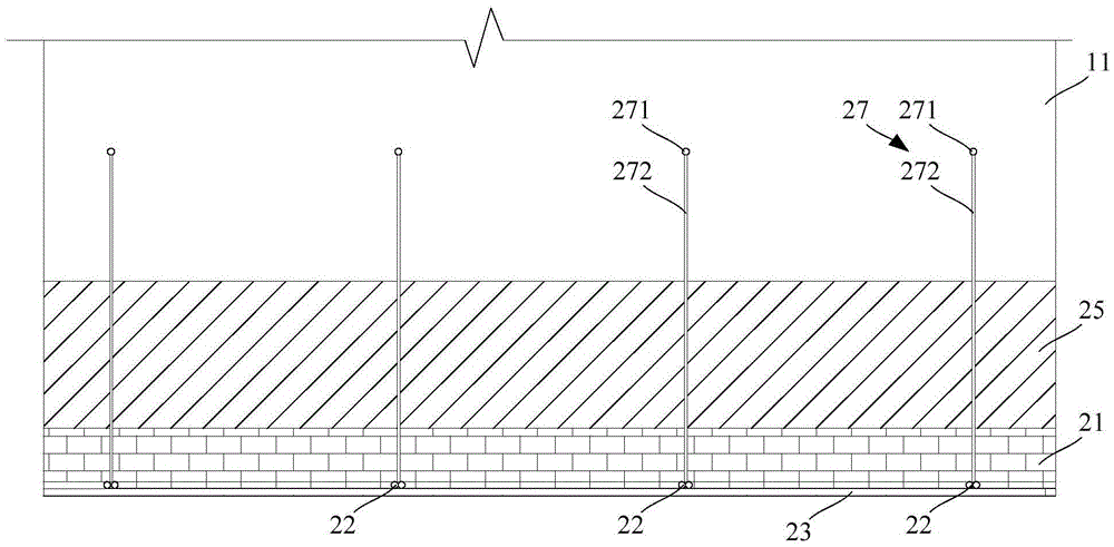
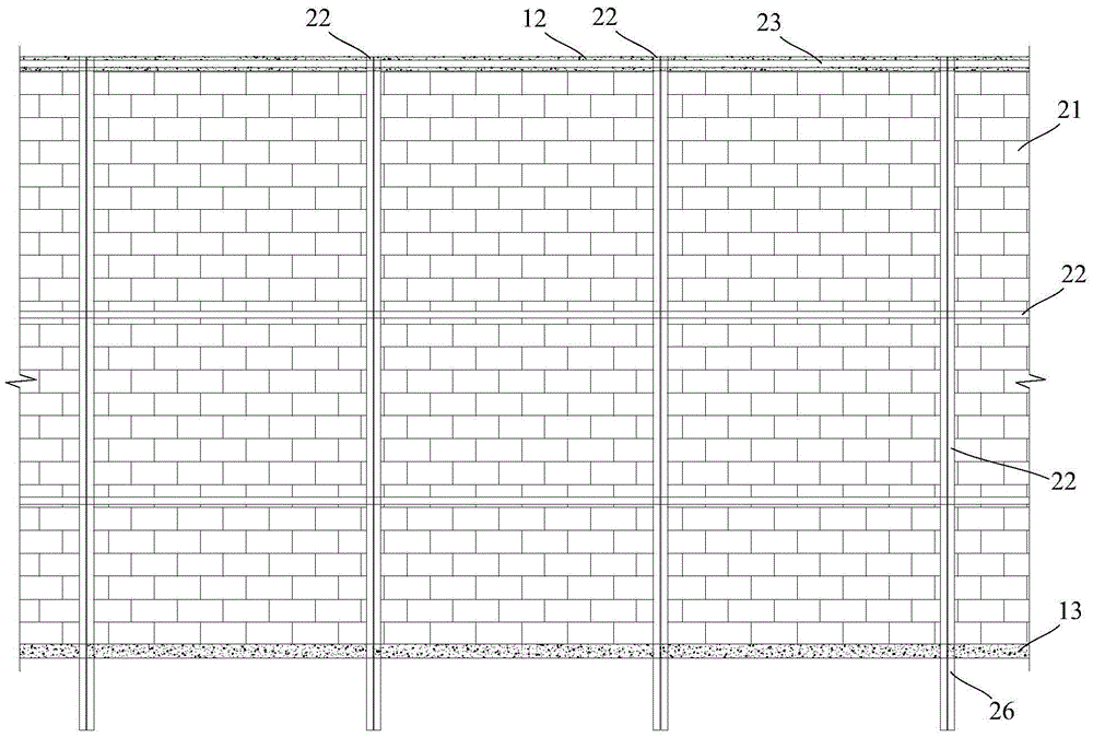
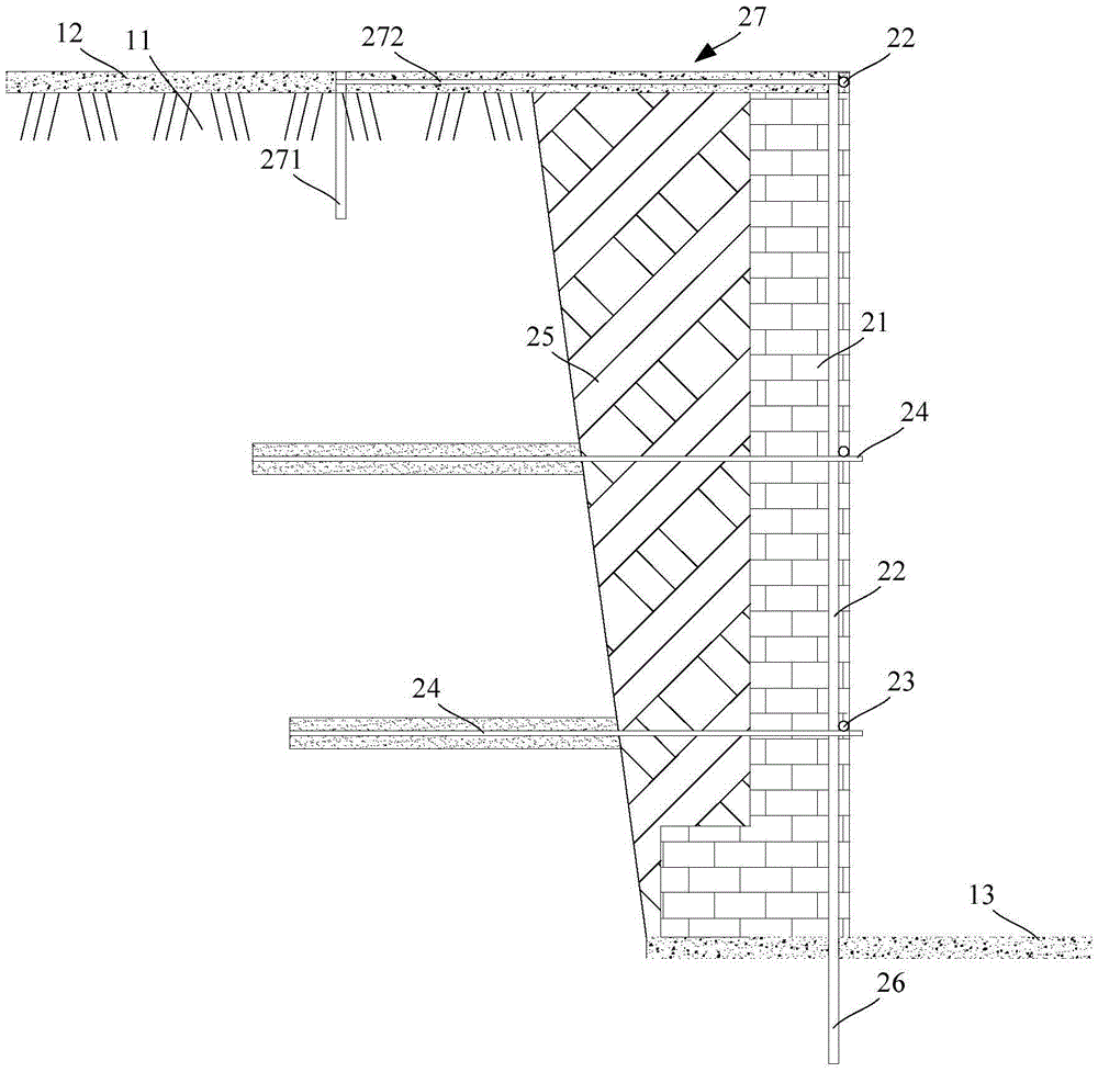
[0037] The invention provides a retaining wall structure with steel pipe ribs and a construction method thereof. The method of using steel pipe ribs instead of structural columns and ring beams reduces the amount of formwork support, steel bar binding and concrete pouring in the construction process, which is effective The construction period is shortened, and the cost is saved to a certain extent. In the present invention, through the connection of horizontal and vertical steel pipe ribs, a mesh-like overall stiffening frame with a certain rigidity is formed, which constrains the retaining wall and achieves the functions of structural columns and waist beams. Below in conjunction with accompanying drawing, the retaining wall structure and construction method of steel pipe rib of the present invention are described.

[0038] refer to figure 1...


PUM


Abstract

The invention relates to an earth-retaining wall structure with steel tube reinforcing ribs and a construction method for the earth-retaining wall structure. The earth-retaining wall structure comprises a brick earth-retaining wall, vertical steel tube reinforcing ribs, transverse steel tube reinforcing ribs, earth nails and backfilled earth, wherein the brick earth-retaining wall is arranged in the side edge of a foundation pit; the vertical steel tube reinforcing ribs are vertically arranged in the brick earth-retaining wall, are close to the inner side surface of the brick earth-retaining wall, are arranged in a spacing manner in a direction of the brick earth-retaining wall, are fixedly connected to the ground, and are internally poured with mortar; the transverse steel tube reinforcing ribs are connected to the vertical steel tube reinforcing ribs; the transverse steel tube reinforcing ribs and the vertical steel tube reinforcing ribs form a vertically-transversely crossed net-shaped structure; the earth nails are arranged in the spacing manner along the height of the vertical steel tube reinforcing ribs; the earth nails pass through the outer side surface of the brick earth-retaining wall and are embedded into rock-soil around the foundation pit; and the gap between the brick earth-retaining wall and the inner wall of the foundation pit is filled with the backfilled earth. The earth-retaining wall structure has relatively high economical efficiency, relatively high reliability and a relatively high efficiency ratio, is simple in structure, and the construction period is shortened.

Description

technical field [0001] The invention relates to the field of building construction, in particular to a steel pipe rib rib retaining wall structure and a construction method thereof. Background technique [0002] In general engineering, using ordinary clay bricks to build the excavation retaining wall of the fertilizer tank in the basement is a more commonly used construction scheme because it is convenient to obtain materials and the cost is relatively low. The retaining wall is subject to the lateral earth pressure of the backfill soil. The higher the wall, the greater the earth pressure, and the greater the bending moment and shear force generated by the earth pressure. Due to the low bending and shear bearing capacity of the brick masonry itself, the height of the wall is greatly limited. Under the premise of satisfying the quality and safety of the wall, corresponding structural measures will be taken, such as setting structural columns, waist beams, top beams, interval...

Claims


Application Information

Patent Timeline
Patent Type & Authority Applications(China)
IPC IPC(8): E02D29/02
CPCE02D29/0275
Inventor 钱德波陈界羽赵亚军杭宏飞魏爱生王晓丽程银行
Owner CHINA CONSTR EIGHT ENG DIV CORP LTD
Learn More