Magnetic levitation type portal crane device

A door machine and maglev technology, which is applied to the suspension device of the wing leaf, door/window accessories, power control mechanism, etc., can solve the problem that the strength is not enough to meet the support needs, the wear resistance cannot meet the long life requirements, and it is easy to deform and other problems to achieve the effect of reducing quality, preventing rust and corrosion, and prolonging the service life

Inactive Publication Date: 2016-06-08
NINGBO INST OF MATERIALS TECH & ENG CHINESE ACADEMY OF SCI
View PDF8 Cites 0 Cited by
  • Summary
  • Abstract
  • Description
  • Claims
  • Application Information

AI Technical Summary

Problems solved by technology

Therefore, those skilled in the art understand that when this driving technology is used in heavy-duty occasions, if the guide rail material is made of plastic or other materials, its strength is far from enough to meet the support needs, and its wear resistance is far from meeting the long-life requirement. , and there are problems such as easy deformation

Method used


Image

  • Magnetic levitation type portal crane device
  • Magnetic levitation type portal crane device
  • Magnetic levitation type portal crane device

Examples


Embodiment 1

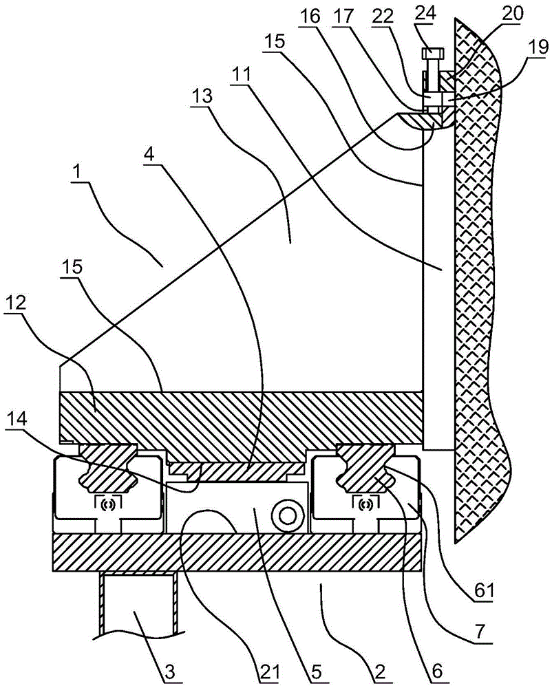
[0046] In this embodiment, the structure of the magnetic levitation door machine device is as follows: figure 1 as shown ( figure 1 is a section of the magnetic levitation door machine device, which is perpendicular to the moving direction of the mobile door), including a fixed support module 1 fixedly connected to the vertical wall, a mobile module 2 slidably connected to the fixed support module, and Mobile door 3 attached to the lower side of the mobile module.

[0047] The fixed support module includes an installation wallboard 11, a base plate 12 and several connecting plates 13 connecting the base plate and the installation wallboard. The installation wallboard is vertically arranged and fixedly connected with the wall. The base plate 12 is horizontally connected to the lower edge of the installation wall panel 11, so that the base plate 12 and the installation wall panel 11 form an L-shaped connection. Modular production, and simplify design, manufacture and maintenan...

Embodiment 2

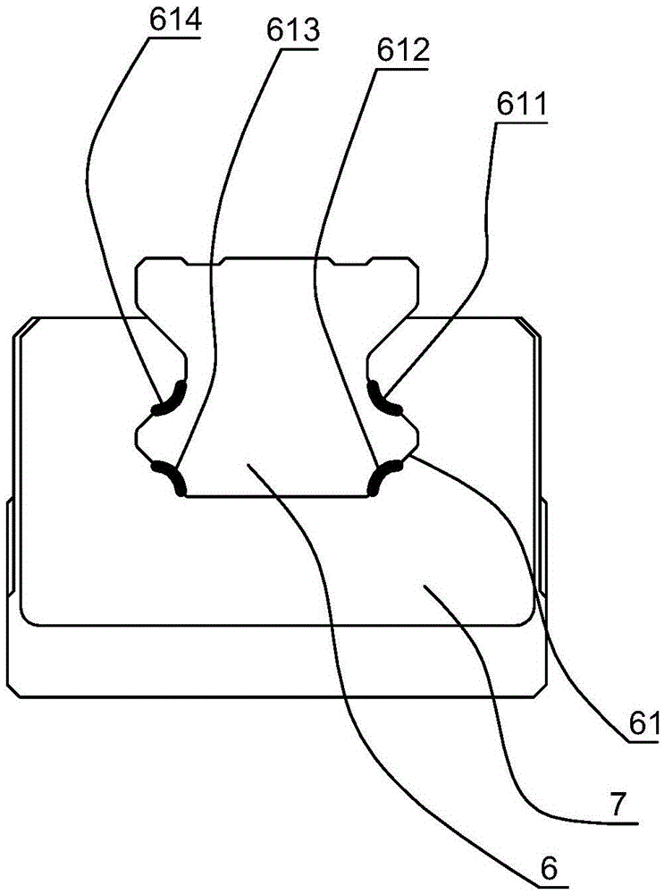
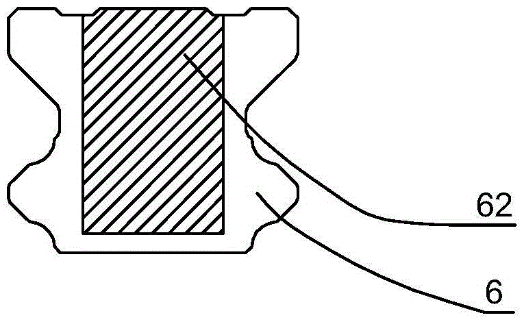
[0057] In this embodiment, the structure of the magnetic levitation door machine device is basically the same as that in Embodiment 1, the difference is that the structure of the guide rail is as follows: Figure 7 As shown, the guide rail is provided with six guide rail working surfaces to match it, and the slider is provided with six slider working surfaces. The paired guide rail working surfaces match the shape of the slider working surface. When the slider slides guided by the guide rail, it passes The working surfaces of the paired guide rails are in contact with the working surfaces of the slider to form six contact working surfaces 611 , 612 , 613 , 614 , 615 and 616 , so as to provide limit in the up-down direction and limit in the left-right direction. The material of the working surface of each guide rail is polyether ether ketone plastic, and the material of the working surface of each slider is polyether ether ketone plastic. Such as Figure 7 As shown, the six wo...


PUM


Abstract

The invention provides a magnetic levitation type portal crane device. The magnetic levitation type portal crane device comprises a flat plate type linear motor stator, a flat plate type linear motor rotor and a movable door. The stator is fixed to the portion above the rotor. Guide rails are arranged on the two sides of the stator. Sliding blocks are arranged on the two sides of the rotor. The guide rails and the sliding blocks are provided with a plurality of work faces made of plastic materials, and the guide rail work faces and the sliding block work faces are matched in shape and arranged in pairs. When the sliding blocks slide with the guide rails as the guide, the sliding block work faces make contact with the guide rail work faces, then limiting in the up-and-down direction and limiting in the left-and-right direction are provided, the cost of the sliding blocks and the guide rails can be reduced, and the mass can be reduced; and meanwhile the installing danger can be avoided, the service life of the sliding blocks and the guide rails is prolonged, and the problem that the contact work faces of the sliding blocks and the guide rails are partly rusted can be prevented.

Description

technical field [0001] The invention relates to a door machine system, in particular to a driving mechanism of the door machine system. Background technique [0002] Existing door machine devices are generally driven by rotary motors. Therefore, it is necessary to convert the rotation of the motor into the linear motion of the door through transmission devices such as racks and pinions, lead screws, synchronous belts, and chains. Due to the existence of mechanical wear and mechanical clearance in this indirect drive mode, and the large inertia of the transmission device, the accuracy and stability of its motion are not high, the starting speed is slow, and the service life is short. Regular maintenance or replacement of the transmission device is required, especially In some large-travel, heavy-duty gate airport occasions, the above-mentioned problems will be more prominent. [0003] Authorized announcement number is that the Chinese patent document of CN201605942U disclose...

Claims


Application Information

Patent Timeline
Patent Type & Authority Applications(China)
IPC IPC(8): E05D15/06E05F15/60
CPCE05D15/0686E05D15/0682E05D2015/0695E05F15/60E05Y2900/132
Inventor 黄彬彬张驰杨桂林廖有用
Owner NINGBO INST OF MATERIALS TECH & ENG CHINESE ACADEMY OF SCI
Why Eureka
Try Eureka