
A wheel hub oil pump mechanism

A technology of wheel hub and oil pump, applied in the direction of mechanical equipment, slack adjuster, brake type, etc., can solve the problem that oil-cooled disc brake cannot be implemented.

Active Publication Date: 2017-12-01
江朝汽车(金湖)有限公司
View PDF5 Cites 0 Cited by
  • Summary
  • Abstract
  • Description
  • Claims
  • Application Information

AI Technical Summary

Problems solved by technology

[0004] The technical problem to be solved by the present invention is to provide a wheel hub oil pump mechanism, which can solve the problems in many aspects in the prior art of installing the oil pump mechanism on the brake, wheel hub or axle housing, which leads to the problem that the oil cooling disc brake cannot be implemented

Method used


Image

  • A wheel hub oil pump mechanism

Examples


Embodiment Construction

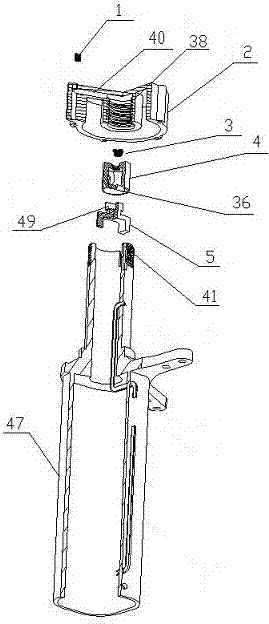
[0016] Such as figure 1 The hub oil pumping mechanism shown includes a hub (not shown) that is rotatably connected to the axle housing 47, the hub is connected with the axle head cover 2, and also includes a drive block 5 connected to the end of the axle housing 47, The screw oil groove 38 connected to the shaft head cover 2, and the shaft head cover core 4 whose one end is connected to the drive block 5 and the other end is inserted into the screw oil groove 38, there is a gap between the shaft head cover core 4 and the screw oil groove 38, and the screw head The inner wall of the oil groove 38 is provided with threads opposite to the rotation direction of the hub, and the shaft head cover 2 is also provided with an oil passage 40 whose oil inlet is located in the helical oil groove 38 . The driving block 5 is composed of a center column, pins vertically extending from both ends of the center column to one side, and a protrusion extending vertically from the middle of the cen...


PUM


Abstract

The invention discloses a wheel hub oil-pumping mechanism which comprises a wheel hub rotatably connected to an axle housing. An axle head cover is connected to the wheel hub. The wheel hub oil-pumping mechanism further comprises a driving block connected to the end of the axle housing, a spiral oil tank connected to the axle head cover and an axle head cover core with one end connected to the driving block and the other end inserted into the spiral oil tank, wherein a gap is reserved between the axle head cover core and the spiral oil tank, threads opposite to the wheel hub in rotating direction are arranged on the inner wall of the spiral oil tank, and an oil way with an oil inlet located in the spiral oil tank is further formed in the axle head cover. In the running process of a vehicle, the axle head cover core is kept in a static state, the spiral oil tank rotates with a wheel hub assembly, and relative motion produced by the threads on the inner wall of the spiral oil tank and the outer wall of the axle head cover core causes extrusion to heat conducting oil to make the oil flow. In addition, due to the fact that the heat conducting oil is more viscous, the lower the vehicle speed is, the larger the cutting force of the threads is, the higher the oil-pumping speed is, additional energy supply is not needed, and no operating cost is produced.

Description

technical field [0001] The invention relates to the field of automobiles, in particular to a wheel hub oil pump mechanism. Background technique [0002] Automobile brakes are divided into two categories: hub type and disc type, both of which are friction type, that is, the driving vehicle is braked by friction. The disc brake is an open structure, and the brake caliper rubs from both sides of the brake disc. The heat generated during the friction process accumulates rapidly. When the vehicle brakes continuously, especially when the vehicle brakes continuously on a long slope, the The temperature of the disc gradually rises to hundreds of degrees Celsius, which will cause the brake disc to overheat and crack, and the brake pads will be ablated to cause the brake to fail. cause a fire accident. [0003] In the prior art, ventilation holes are generally provided on the brake disc to realize heat dissipation through air circulation; as we all know, the heat dissipation effect ...

Claims


Application Information

Patent Timeline
Patent Type & Authority Patents(China)
IPC IPC(8): F16D65/78
CPCF16D65/78F16D2065/783
Inventor 郑成虎
Owner 江朝汽车(金湖)有限公司
Learn More