Cam constant force mechanism

A cam mechanism, cam technology, applied in mechanical equipment, belts/chains/gears, transmissions, etc., can solve the problems of low reliability, complex structure, large volume, etc., achieve simple principle and structure, compact structure, reliable high sex effect

Inactive Publication Date: 2016-06-08
SICHUAN UNIV
View PDF5 Cites 7 Cited by
  • Summary
  • Abstract
  • Description
  • Claims
  • Application Information

AI Technical Summary

Problems solved by technology

Mechatronic control can achieve precise control of force through feedback, but in general, the structure is more complicated, the volume is larger, and the reliability is not high
The gravity balance method uses the gravity of the weight as the input of the constant force, which can obtain high precision, but this kind of device has high requirements for the installation position, and it is difficult to meet the actual application conditions

Method used


Image

  • Cam constant force mechanism
  • Cam constant force mechanism
  • Cam constant force mechanism

Examples


Embodiment Construction

[0016] The present invention will be further described below in conjunction with the accompanying drawings and specific embodiments.

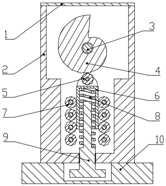
[0017] like figure 1 As shown, the cam constant force mechanism described in this embodiment includes a base and a cam mechanism: the base is composed of a cover plate 1, a housing 2 and a chassis 10; the cover plate 1, the housing 2 and the chassis 10 are fixed in sequence; the cam mechanism It is composed of screw 9, spring 8, push rod 6, roller 5 and cam 4; the screw 9, spring 8, and push rod 6 are connected in sequence, the screw 9 is screwed with the bottom of the shell 2, and the cam 4 is connected with the camshaft 3 is fixedly connected and installed inside the housing 2, the roller 5 is installed on the top of the push rod 6 and is in contact with the cam 4; the inside of the housing 2 is also equipped with a bearing 7, and the bearing 7 is centered on the push rod 6 to work on the cam 4 They are arranged symmetrically on the plane, a...


PUM


Abstract

The invention provides a cam constant force mechanism. The constant force mechanism comprises a base and a cam mechanism. The base is composed of a cover plate, a shell and a bottom plate. The cover plate, the shell and the bottom plate are sequentially fixedly connected. The cam mechanism is composed of a screw, a spring, a push rod, a roller, a cam shaft and a cam. The screw, the spring and the push rod are sequentially connected. The screw is screwed with the bottom of the shell through a thread. The cam is fixedly connected with the cam shaft and installed inside the shell. The roller is arranged on the top of the push rod and makes contact with the cam. The cam contour line of the cam meets the condition that the torque, generated for the center of the cam, of the roller is kept constant when the cam rotates. The cam constant force mechanism has the beneficial effects of being compact in structure, small in size, high in reliability, capable of not being limited by the installing position, and the like.

Description

technical field [0001] The invention relates to a constant force loading mechanism, in particular to a cam constant force mechanism. Background technique [0002] Constant force mechanism is a device that still outputs a basic constant force when the load generates displacement. Because it does not satisfy Hooke's theorem, it is essentially different from traditional cylindrical springs or other elastic bodies. It has been widely used in machinery, nuclear Industry, national defense and military, instrumentation and many other fields that require constant force output, such as mechanical support mechanism, nuclear power plant pipeline, artillery automatic machine, printing machine paper transfer mechanism, etc., have an important impact on the safety and reliability of equipment. And the method that can obtain constant force at present has: methods such as mechatronics control, gravity balance. Mechatronics control can achieve precise force control through feedback, but in ...

Claims


Application Information

Patent Timeline
Patent Type & Authority Applications(China)
IPC IPC(8): F16H25/10F16H25/14
CPCF16H25/10F16H25/14
Inventor 黄春强李斌叶北发姚进
Owner SICHUAN UNIV
Why Eureka
Try Eureka