Improved split faucet

An improved faucet technology, which is applied in the field of faucets, can solve problems such as freezing cracks, difficulty in locking nuts, and cracks, and achieve the effects of preventing expansion and shrinkage, increasing connection stability, and convenient installation and use.

Active Publication Date: 2017-07-21
黄振波
View PDF1 Cites 4 Cited by
  • Summary
  • Abstract
  • Description
  • Claims
  • Application Information

AI Technical Summary

Problems solved by technology

The known faucet valve body and valve core are generally integrally cast with brass or zinc alloy. The casting process requires high production technology and complicated processing, and the casting material contains toxic heavy metal lead chemical components, which cannot meet the requirements of national standards. It is not conducive to environmental protection and affects human health; in addition, it is all made of multi-metal materials, the cost of materials is high, and the anti-corrosion effect of metal water channels is not good, which will affect the taste of water after a long time of use
[0003] In order to solve the above technical problems, Chinese patent number: 201420488167.2 discloses an improved split faucet, which includes a zinc alloy valve housing and a plastic valve core seat sleeved in the zinc alloy valve housing, the plastic valve core seat The lower end is provided with a cylindrical threaded sleeve for passing through the installation hole of the sink. The threaded sleeve is equipped with a lock nut matching the thread. The improved split faucet adopts a plastic valve core seat (plastic inner tube) and a zinc alloy valve. The shell (metal shell) is combined and installed separately, which is easy to manufacture, reduces the production process requirements during casting, simplifies the processing process, saves labor costs, improves production efficiency, and solves the problem of poor anti-corrosion effect of the metal inner wall. After a long time, the problem of affecting the taste of water quality, but the split faucet still has the following defects during use:
[0004] 1. The inner core of the water is made of a plastic valve core seat. The plastic inner tube is affected by cold air or cold water, and will become brittle at low temperatures. Because the plastic inner tube will shrink due to heat and cold, it is easy to be stretched out when the water pressure is unstable. Cracks, frost cracks appear, the service life is extremely short, and the applicability is not strong in places with cold weather
[0005] 2. After the zinc alloy valve shell and the plastic valve core seat are installed, there is a gap between the two, and the gap between the two will have moist air or moisture after the plastic valve core seat is frozen and cracked. The main component of the shell is zinc alloy, which is an amphoteric metal with poor chemical stability. It is very easy to oxidize and corrode in humid air, and its service life is also very limited.
[0006] 3. Because the plastic inner core is made of plastic material, and after the zinc alloy valve housing and the plastic valve core seat are installed, there is a gap between the two, which makes the texture of the improved faucet very poor, light in weight, and easy to lock The nut and the threaded sleeve at the bottom of the plastic valve core seat are made of different materials. It is difficult to screw the lock nut on the threaded sleeve of the plastic valve core seat, the connection is not firm, and the overall stability is not good. In addition, due to the weight of the split faucet Very light, after installing the split faucet on the washbasin, when turning the outlet pipe above the split faucet, the phenomenon that the entire split faucet will rotate with the outlet pipe is easy to occur, which is very troublesome for users and seriously affects their The market is very popular, and when the whole faucet rotates with the upper outlet pipe, the bottom of the plastic valve core seat will break.

Method used


Image

  • Improved split faucet
  • Improved split faucet
  • Improved split faucet

Examples


Embodiment

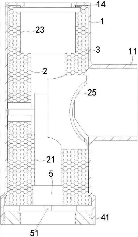
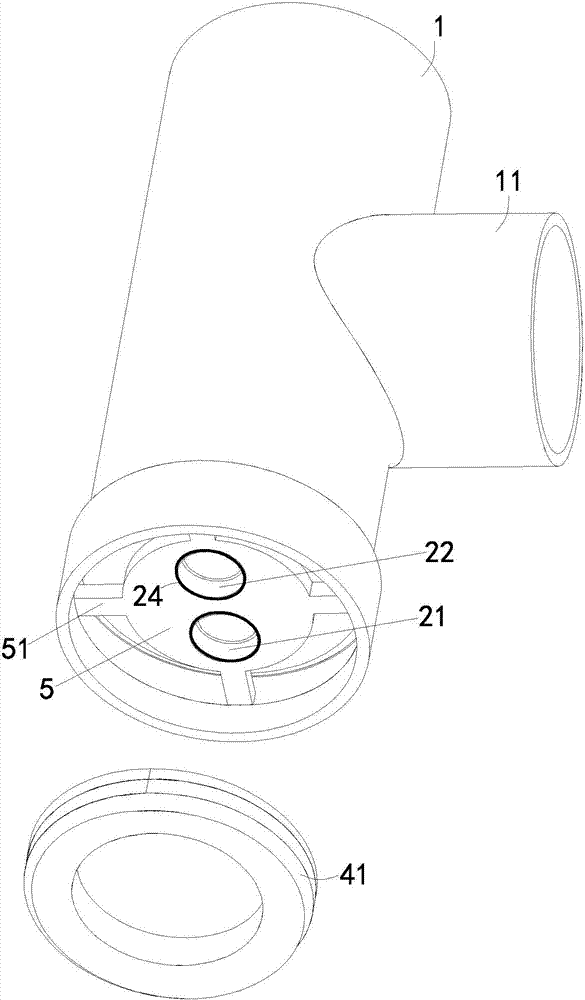
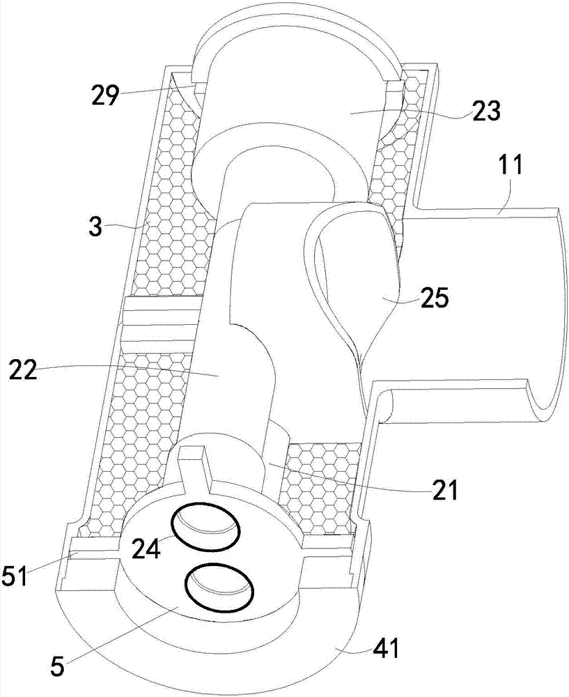
[0030] Such as Figure 1 to Figure 4 , the embodiment of the present invention discloses an improved split faucet, including a zinc alloy faucet body 1 and a plastic inner valve core tube 2 disposed in the zinc alloy faucet body 1, and the plastic inner valve core tube 2 can be pc polycarbonate or pp polypropylene or POM polyoxymethylene plastic inner valve core tube, in this embodiment, pc polycarbonate plastic inner valve core tube is used, the zinc alloy faucet body 1 has a hollow inner cavity, and one side of the middle part of the zinc alloy faucet body 1 A spool installation pipe 11 is provided, and the plastic inner spool pipe 2 is provided with a water inlet pipe and an outlet pipe 23 along the axial direction, and the water inlet pipe includes a cold water inlet pipe 21 and a hot water inlet pipe 22, and the cold water inlet pipe and the The inner cavity at the bottom of the hot water inlet pipe is provided with a copper sleeve 24, and the inner wall of the copper sle...


PUM


Abstract

The invention discloses an improved split faucet which adopts a simple production technology and is low in material cost, long in service life and good in mounting and positioning effect. The improved split faucet comprises a metal faucet body and an internal plastic valve core tube arranged in the metal faucet body, wherein a valve core mounting tube is arranged on one side of the middle of the metal faucet body; the internal plastic valve core tube is provided with water inlet tubes and a water outlet tube in an axial direction and is inserted into the metal faucet body; a water outlet valve seat of the internal plastic valve core tube corresponds to the valve core mounting tube of the metal faucet body; a gap between the internal plastic valve core tube and the metal faucet body is filled with an anti-freezing protection layer; copper bushes are arranged in inner cavities in the bottoms of the water inlet pipes, and copper hole threads are formed on inner walls of the copper bushes; an axial positioning device capable of preventing the internal plastic valve core tube from axial displacement and a radial positioning device capable of limiting radial rotation of the internal plastic valve core tube are further arranged between the internal plastic valve core tube and the metal faucet body.

Description

technical field [0001] The invention relates to the field of faucets, in particular to an improved split faucet. Background technique [0002] As known, the existing faucet includes a valve body, a water inlet pipe and an outlet pipe connected with the valve body, and water flows from the water inlet pipe into the valve body through the valve core in the valve body, and then flows out from the water outlet pipe. The known faucet valve body and valve core are generally integrally cast with brass or zinc alloy. The casting process requires high production technology and complicated processing, and the casting material contains toxic heavy metal lead chemical components, which cannot meet the requirements of national standards. It is not conducive to environmental protection and affects human health; in addition, it is all made of multi-metal materials, the cost of materials is high, and the anti-corrosion effect of the metal flow channel is not good, and the water quality will...

Claims


Application Information

Patent Timeline
Patent Type & Authority Patents(China)
IPC IPC(8): F16K27/00F16K11/00
CPCF16K19/006F16K27/00
Inventor 黄振波
Owner 黄振波
Why Eureka
Try Eureka