Novel single-row tube bank for cooling air

A new type of air cooling technology, applied in tubular components, lighting and heating equipment, heat exchange equipment, etc., can solve the problems of increased system cleaning times, high raw material cost, large base pipe cross-section, etc., to ensure thermal conductivity, reduce Enhanced heat exchange efficiency and antifreeze capability

Inactive Publication Date: 2013-01-23
HUADIAN HEAVY IND CO LTD +1
View PDF6 Cites 6 Cited by
  • Summary
  • Abstract
  • Description
  • Claims
  • Application Information

AI Technical Summary

Problems solved by technology

[0003] The base tube of the existing heat exchanger is an elliptical flat tube, the flow channel on the air side is long, the resistance is large, and the cross section of the base tube is large, resulting in high cost of raw materials; the air in the channel is mostly in a laminar flow state, which is easy to accumulate dust and increase The cleaning times of the system; the dust falling into the fins is more likely to affect the heat transfer intensity
[0004] There will be laminar flow and turbulent flow during heat exchange of single row tubes. The heat transfer rate is low in laminar flow and high in turbulent flow. How to rely on turbulent flow to achieve higher heat transfer effect has been a research topic for a long time.

Method used


Image

  • Novel single-row tube bank for cooling air
  • Novel single-row tube bank for cooling air
  • Novel single-row tube bank for cooling air

Examples


Embodiment 1

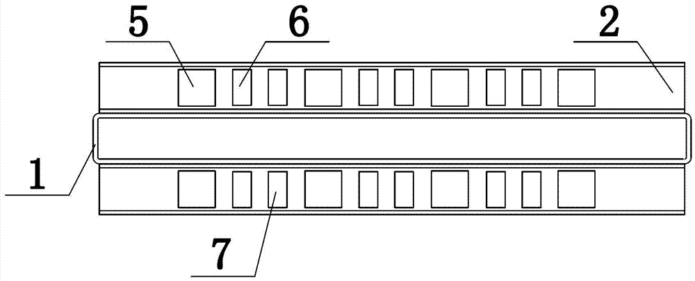
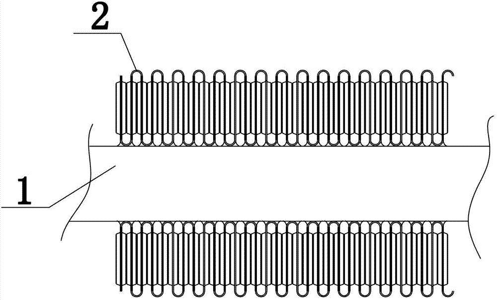
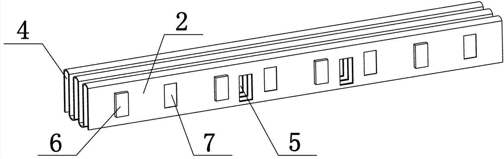
[0029] Embodiment 1 of the present invention: as figure 1 , figure 2 As shown, a new type of single-row tube bundle for air cooling, including a base tube 1 and fins 2, the base tube 1 is a rectangular flat tube with chamfers, the fins 2 are arranged on the upper and lower surfaces of the base tube 1, the base tube 1 The fins 2 are welded together by integral brazing, the fins 2 are serpentine, and the fins 2 are provided with spoiler holes 5 .

[0030] The number of spoiler holes 5 on the fin 2 is an even number, and the spoiler holes 5 are evenly distributed on the fin 2 .

[0031] The shape of the spoiler hole 5 is rectangular.

[0032] The fins 2 are also provided with protrusions 6 and grooves 7 , and the protrusions 6 and grooves 7 are alternately distributed on the fins 2 .

[0033] Such as Figure 5 As shown, the spoiler hole 5 is provided with a spoiler 3 having the same shape as the spoiler hole.

[0034] Such as Figure 7 As shown, the angle α between the spo...

Embodiment 2

[0040] Embodiment 2 of the present invention: as figure 1 , figure 2 As shown, a new type of single-row tube bundle for air cooling, including a base tube 1 and fins 2, the base tube 1 is a rectangular flat tube with chamfers, the fins 2 are arranged on the upper and lower surfaces of the base tube 1, the base tube 1 The fins 2 are welded together by integral brazing, the fins 2 are serpentine, and the fins 2 are provided with spoiler holes 5 .

[0041] The number of spoiler holes 5 on the fin 2 is an even number, and the spoiler holes 5 are evenly distributed on the fin 2 .

[0042] Such as Figure 6 As shown, the shape of the spoiler hole 5 is a triangle.

[0043] The fins 2 are also provided with protrusions 6 and grooves 7 , and the protrusions 6 and grooves 7 are alternately distributed on the fins 2 .

[0044] A spoiler 3 having the same shape as the spoiler hole is provided on the spoiler hole 5 .

[0045] Such as Figure 7 As shown, the angle α between the spoil...

Embodiment 3

[0051] Embodiment 3 of the present invention: as figure 1 , figure 2 As shown, a new type of single-row tube bundle for air cooling, including a base tube 1 and fins 2, the base tube 1 is a rectangular flat tube with chamfers, the fins 2 are arranged on the upper and lower surfaces of the base tube 1, the base tube 1 The fins 2 are welded together by integral brazing, the fins 2 are serpentine, and the fins 2 are provided with spoiler holes 5 .

[0052] The number of spoiler holes 5 on the fins 2 is an even number.

[0053] The shape of the spoiler hole 5 is rectangular.

[0054] The fins 2 are also provided with protrusions 6 and grooves 7 , and the protrusions 6 and grooves 7 are alternately distributed on the fins 2 .

[0055] Such as Figure 5 As shown, the spoiler hole 5 is provided with a spoiler 3 having the same shape as the spoiler hole.

[0056] Such as Figure 7 As shown, the angle α between the spoiler 3 and the fin 2 is 30°.

[0057] The material of the base...


PUM


Abstract

The invention discloses a novel single-row tube bank for cooling air, which comprises a base tube and fins, wherein the fins are arranged on the upper surface and the lower surface of the base tube, the base tube is a rectangular flat tube with chamfers, the base tube and the fins are welded together through whole soldering, the fins are shapes-shaped, and spoiling holes are formed in the fins. The tube bank has the advantages that as the rectangular flat tube with the chamfers is used as the base tube, the effects of shortening the length of the base tube, saving materials, facilitating cleaning, ensuring heat exchange intensity, reducing stress concentration phenomenon, greatly improving rigidity and protecting the deformed base tube from frost-breaking in winter are realized; and as the spoiling holes are formed in the traditional S-shaped flat fins, the laminar flow state of the single-row tube bank during heat exchange is destroyed by the spoiling holes, heat exchange is carried out on cold air among the fins in a turbulent state, an original boundary layer is destroyed, the uninterrupted exchange of the cold air is enhanced, the convection heat exchange intensity on the side of the fins is greatly increased, the heat exchange efficiency of a heat radiator is improved at the same time, and the heat exchange area of the heat radiator is reduced under the condition of same heat load.

Description

technical field [0001] The invention relates to a novel single-row tube bundle for air cooling, which belongs to air cooling equipment in thermal power plants, chemical industry and air separation industries. Background technique [0002] The heat exchanger of the direct air cooling system is the main part of the system. The medium inside the single-row tube is steam with a higher temperature. The heat is transferred to the lower temperature outside the single-row tube through the fins brazed on the base tube in the air. Its manufacturing quality, operating performance and service life are the main issues in its development process. Since the heat exchanger equipment accounts for about half of the investment in the air-cooling system, the price of the air-cooling heat exchange device, the pros and cons of heat transfer capacity and resistance performance, and the length of service life play a decisive role in the safe and economical operation of the air-cooling unit. [00...

Claims


Application Information

Patent Timeline
Patent Type & Authority Applications(China)
IPC IPC(8): F28F1/04F28F1/12F28F13/02
Inventor 闫平邢苍汉伯・汉博瑞格茨刘学李国栋
Owner HUADIAN HEAVY IND CO LTD
Why Eureka
Try Eureka