cooling system

A cooling system and cooling unit technology, applied in the field of metallurgy, can solve the problems of large water flow resistance and safety hazards, and achieve the effects of reducing liquid flow resistance, safety hazards, and safety production accidents

Active Publication Date: 2017-12-19
CHINA ENFI ENGINEERING CORPORATION
View PDF6 Cites 0 Cited by
  • Summary
  • Abstract
  • Description
  • Claims
  • Application Information

AI Technical Summary

Problems solved by technology

[0004] The main purpose of the present invention is to provide a cooling system to solve the problems of large water flow resistance and safety hazards when positive pressure cooling is used

Method used


Image

  • cooling system

Examples


Embodiment Construction

[0021] It should be noted that the embodiments in the application and the features in the embodiments can be combined with each other if there is no conflict. Hereinafter, the present invention will be described in detail with reference to the drawings and in conjunction with the embodiments.

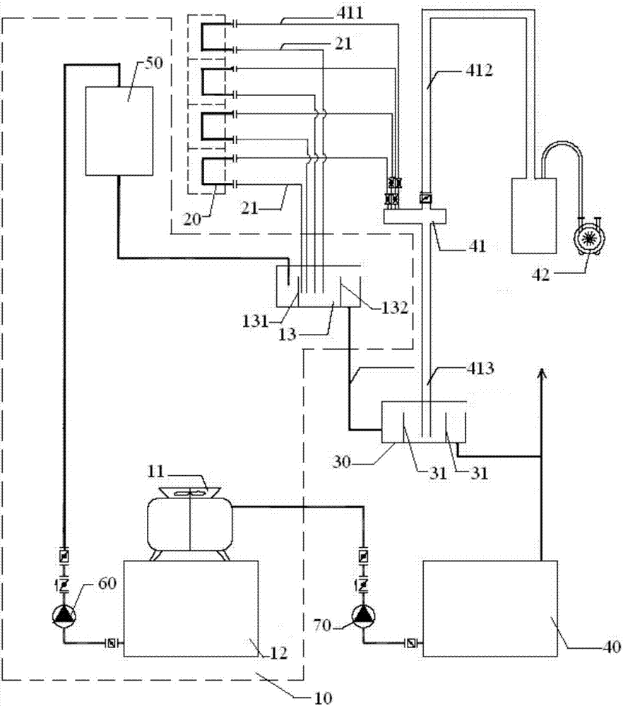
[0022] As described in the background art, the existing positive pressure cooling has the problems of large water flow resistance and high safety risks. In order to solve the above technical problems, the present invention provides a cooling system, such as figure 1 As shown, the cooling system includes: a refrigerant supply unit 10, a cooling unit 20 for cooling an object to be cooled, a liquid sealing tank 30, and a refrigerant recovery unit 40. The cooling unit 20 and the refrigerant supply unit 10 are connected through a refrigerant input pipe 21; the refrigerant recovery unit 40 includes a refrigerant recovery pipe group 41 and a vacuum pump group 42. The refrigerant recovery pipe g...


PUM


Abstract

A cooling system comprises a refrigerant supply unit (10), a cooling unit (20) used for cooling a to-be-cooled object, a liquid seal groove (30) and a refrigerant recycling unit (40). The cooling unit (20) communicates with the refrigerant supply unit (10) through a refrigerant input pipe (21). The refrigerant recycling unit (40) comprises a refrigerant recycling pipe set (41) and a vacuum pump set (42). The refrigerant recycling pipe set (41) comprises a refrigerant recycling branch pipe (411), a vacuum pipe (412) and a siphon (413), all of which communicate with one another through the same port. The vacuum pump set (42) is connected with the vacuum pipe (412). The refrigerant recycling branch pipe (411) communicates with the cooling unit (20). The siphon (413) communicates with the liquid seal groove (30). The horizontal plane where the refrigerant supply unit (10) is located is higher than the horizontal plane where the liquid seal groove (30) is located. Due to the fact that a certain height difference exists between the refrigerant supply unit (10) and the liquid seal groove (30), cooling water in the refrigerant supply unit (10) can overcome resistance of a pipeline and enters the liquid seal groove (30) by itself. Due to the fact that the whole cooling system is in negative pressure, when the cooling unit is fractured, a refrigerant cannot overflow or hardly overflows, and accordingly production accidents caused by refrigerant overflow can be better reduced.

Description

Technical field [0001] The invention relates to the field of metallurgy, in particular to a cooling system. Background technique [0002] In the metallurgical process, it is necessary to cool the lining of the pyrometallurgical furnace to keep the temperature of the furnace lining at a lower temperature, which is beneficial to slow down the corrosion of the furnace body, so as to achieve the purpose of extending the life of the furnace body. Normally, the positive pressure cooling method is used for cooling. Positive pressure cooling means that the water pressure in the pipeline from the water inlet to the outlet of the cooling water system is always higher than one atmosphere. In this environment, the pressure and flow of the cooling water are adjusted to achieve the purpose of removing the surface heat of the cooled object in time. [0003] Positive pressure cooling has the characteristics of simple operation, easy adjustment of water pressure and water volume, and obvious cooli...

Claims


Application Information

Patent Timeline
Patent Type & Authority Patents(China)
IPC IPC(8): F27D1/12
CPCF27D1/12
Inventor 黎敏邬传谷杨晓华陈希勇陈学刚王书晓王兴斌曹珂菲
Owner CHINA ENFI ENGINEERING CORPORATION
Why Eureka
Try Eureka