Spacecraft product final assembly precision measuring method based on workpiece coordinate system

A technology of precision measurement and coordinate system, applied in measurement devices, instruments, optical devices, etc., can solve the problems of cubic mirrors occupying load weight, difficult to process cubic mirrors, low measurement efficiency, etc., to save satellite launch costs and reduce occupation. The effect of load weight and improved measurement efficiency

Active Publication Date: 2016-06-08
HARBIN INST OF TECH
View PDF9 Cites 21 Cited by
  • Summary
  • Abstract
  • Description
  • Claims
  • Application Information

AI Technical Summary

Problems solved by technology

[0014] The present invention aims to solve the problems of low measurement efficiency and high difficulty of the existing theodolite measurement system and

Method used


Image

  • Spacecraft product final assembly precision measuring method based on workpiece coordinate system
  • Spacecraft product final assembly precision measuring method based on workpiece coordinate system
  • Spacecraft product final assembly precision measuring method based on workpiece coordinate system

Examples


specific Embodiment approach 1

[0046] The method for measuring the accuracy of the assembly of spacecraft products based on the workpiece coordinate system includes the following steps:

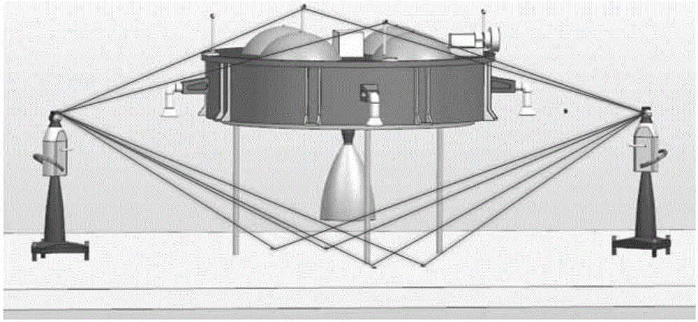
[0047] Step 1. Establishment of the public coordinate system:

[0048] For the main body of the spacecraft that needs to detect the installation accuracy of the components, select several public reference points on the surface of the main body of the spacecraft, select several public reference points on the reference object plane where the main body of the spacecraft is currently located, and select a number of public reference points on the surface of the main body of the spacecraft. An optical reflector, that is, a target ball, is set on the 4-6 public reference points in the points;

[0049] respectively in A 1 and A 2 Position setting laser tracker a 1 and a 2 ;Adjust the laser tracker a through the cooperation of the laser tracker and the target ball 1 Obtain public fiducials on the laser tracker a 1 Coordinate ...

specific Embodiment approach 2

[0056] The specific process of the assembly accuracy of the detection part assembly described in step 3 of the present embodiment is as follows:

[0057] Set multiple target balls on the surface of the component to be inspected many times, set the measurement mode of the laser tracker to the stable point scanning mode, and pass the laser tracker a 1 and a 2 Cooperate with the target ball to scan the components of the part to be detected;

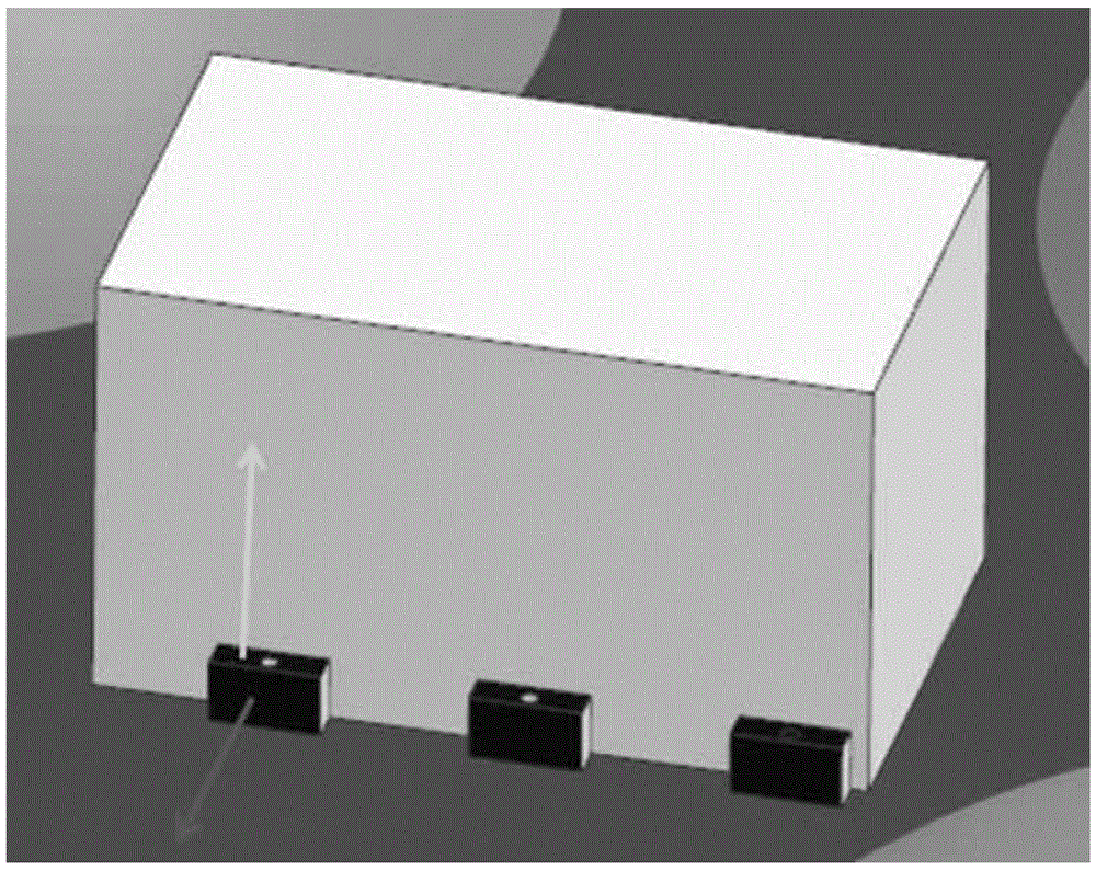
[0058] (1) As shown in Figure 3(a) and (b), if the component to be detected is a cube, combine the measured points and use the SpatialAnalyzer software to perform least squares surface fitting to obtain the normal of the plane, and calculate The angle between the normal line and the corresponding coordinate axis of the reference coordinate system is used to judge the installation accuracy of the components to be detected;

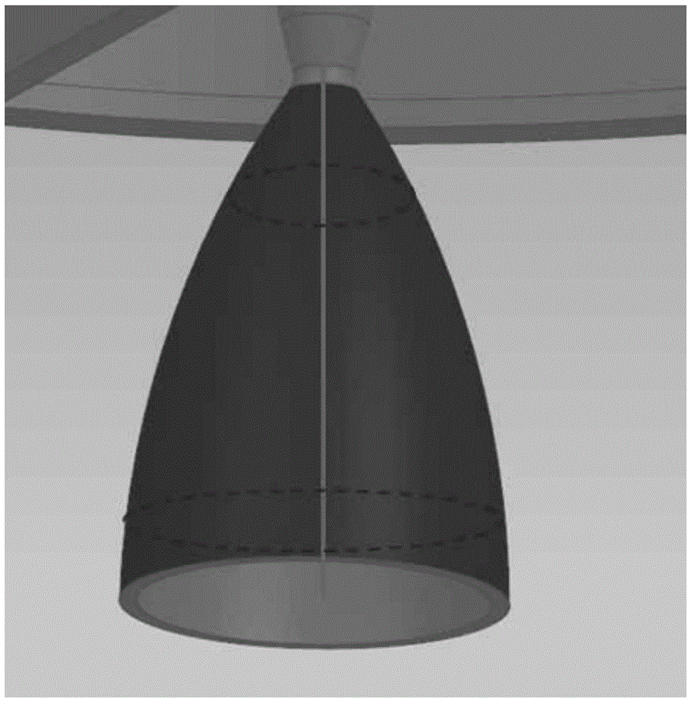
[0059] (2) If the component to be tested is a cylinder or a cone (such as a nozzle with a throat diameter, etc.), not...

specific Embodiment approach 3

[0061] The specific process of detecting the axis installation accuracy of the component to be detected described in (2) of this embodiment is as follows:

[0062] The setting mode of the laser tracker is the point triggered by the geometry. The point triggered by the geometry is the name of the point collection mode of the SpatialAnalyzer software. Points, the points collected outside the plane are automatically eliminated; make the circular measurement object of the cylinder or the flat end face of the vertebral body, as shown in Figure 4 (a) and (b), set multiple target balls on the circular circumference of the flat end face on, or move the target ball on the circular circumference of the flat end surface for measurement, using the laser tracker a 1 and a 2 The obtained points are combined, and the circle fitting is carried out to obtain the center of the circle; the target ball is moved or set around the circumference of the circular contour surface with a flat end surfa...


PUM


Abstract

The invention discloses a spacecraft product final assembly precision measuring method based on a workpiece coordinate system, relates to the field of final assembly precision measurement and particularly relates to a spacecraft product final assembly precision measuring method. The method is used for solving the problems of the existing theodolite measuring system of low measurement efficiency, high difficulty, difficult processing of a cubic mirror, relatively low qualified rate and load weight of the cubic mirror launched with satellite. In the invention, the cubic mirror coordinate system is replaced by a workpiece coordinate system, and the method comprises the following steps: selecting 4-6 public reference points from the public reference points on the spacecraft body surface and the reference object plane; collecting the coordinate data of the public reference points using a laser tracker, and establishing a public coordinate system; performing corresponding spatial geometric processing and establishing a reference coordinate system; and fitting the component surface and calculating the normal of the component surface and the component axis through software using the laser tracker under the reference coordinate system, and performing comparative calculation with the reference coordinate system to obtain the assembly precision of the component. The method disclosed by the invention is applicable to the measurement of spacecraft product final assembly precision.

Description

technical field [0001] The invention relates to the field of assembly accuracy measurement, in particular to a method for measuring the assembly accuracy of aerospace products. Background technique [0002] Assembly precision measurement technology is a powerful means to ensure the overall assembly accuracy of spacecraft, and assembly accuracy measurement is an indispensable and important link in the overall assembly process of spacecraft. [0003] Most spacecraft have complex structures, so the assembly sequence is to assemble the sub-system components first, and then proceed to the overall assembly. The purpose of overall assembly accuracy measurement is to use certain test methods as technical means to detect the linearity of the theoretical axis of the components, the coaxiality of the geometrical surface, the relative position of the sub-system relative to the star, and the sun sensor, gyroscope, Whether the parameters such as the installation orientation of the attitu...

Claims


Application Information

Patent Timeline
IPC IPC(8): G01B11/00
CPCG01B11/002
Inventor 张晓琳唐文彦王军尹寿宝
Owner HARBIN INST OF TECH
Why Eureka
Try Eureka