
Reverse time migration imaging method and apparatus

A technology of reverse time migration imaging and imaging, which is applied in the field of geological exploration and can solve the problems of lack of high-order algorithms and no solutions.

Active Publication Date: 2016-06-08
BC P INC CHINA NAT PETROLEUM CORP +1
View PDF4 Cites 8 Cited by
  • Summary
  • Abstract
  • Description
  • Claims
  • Application Information

AI Technical Summary

Problems solved by technology

[0004] The wave field simulation for the acoustic wave and elastic wave equation is the basis of the migration imaging method based on the wave equation. The commonly used numerical calculation methods include: the finite element method and the finite difference method. Among them, the finite element method has the advantages of Great flexibility, but the downside is that it lacks the ability to apply to high-order algorithms, especially considering frequency-dependent dispersion
[0006] However, how to use changing grids for imaging in the horizontal direction (X\Y) and vertical direction (Z) at the same time, has not yet proposed an effective solution

Method used


Image

  • Reverse time migration imaging method and apparatus
  • Reverse time migration imaging method and apparatus
  • Reverse time migration imaging method and apparatus

Examples


Embodiment Construction

[0057] In order to make the objectives, technical solutions, and advantages of the present invention clearer, the present invention will be further described in detail below in conjunction with the embodiments and the drawings. Here, the exemplary embodiments of the present invention and the description thereof are used to explain the present invention, but not as a limitation to the present invention.

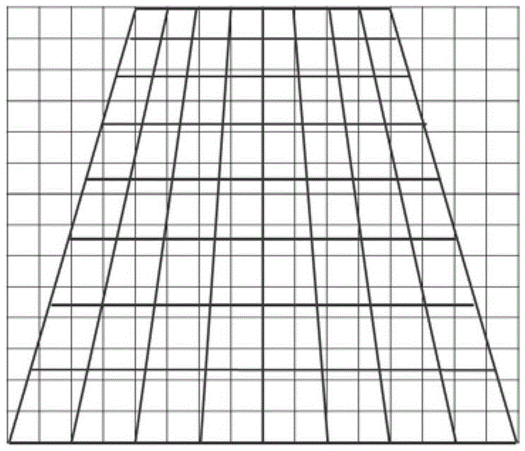
[0058] The inventor considers that a pyramid grid (P-Grid) can be used for imaging, so as to achieve the purpose of simultaneously using a varying grid for imaging in the horizontal and vertical directions.

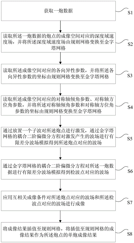
[0059] Specifically, a reverse time migration imaging method is provided, such as figure 1 As shown, including the following steps:

[0060] S1: Obtain the data of a shot, for example, you can get the data of a shot in the task list, and prepare for reverse time migration (RTM) of the shot;

[0061] S2: Read the depth domain velocity field corresponding to the imaging space of t...


PUM


Abstract

The invention provides a reverse time migration imaging method and device. The method includes the following steps that: a shot of data are obtained; a depth domain velocity field is transformed to pyramid grids from regular grids; the coordinates of anisotropy parameters delta and epsilon, a symmetry axis tile angle parameter theta and a symmetry axis azimuth parameter phi are transformed to the pyramid grids from the regular grids; finite difference wave field simulation is performed on a wave field generated by excitation by using a coupling second-order partial differential equation of the pyramid grids, so that a wave field corresponding to a shot point and a wave field corresponding to a detection point can be obtained; imaging is performed on the wave field corresponding to the shot point and the wave field corresponding to the detection point by using a cross-correlation imaging condition; an imaging result is interpolated to the regular grids, the imaging result which has been interpolated to the regular grids is adopted as a single-shot imaging result of the shot point. With the method and device of the invention adopted, the technique problem that changing grids cannot be utilized to perform imaging in a horizontal direction and a vertical direction simultaneously can be solved, and changing grids can be utilized to perform imaging in a horizontal direction and a vertical direction simultaneously in a horizontal direction and a vertical direction.

Description

Technical field [0001] The invention relates to the technical field of geological prospecting, in particular to a reverse time migration imaging method and device. Background technique [0002] Reverse Time Migration (RTM) technology is based on the full acoustic wave equation, fully complies with the physical laws of waves in the acoustic medium, and completely simulates the various wave phenomena in the seismic wave field propagation process with high accuracy, making it more suitable for speed Seismic wave imaging problems in areas with drastic changes and complex structures, especially when there are cyclic waves and prism reflections in the wave field, reverse time migration (RTM) can show advantages over one-way wave equation migration. [0003] Since reverse time migration (RTM) simulates the propagation of seismic waves in the time-space domain through a difference method, this method can be easily and naturally extended to the imaging problems of non-uniform anisotropic me...

Claims


Application Information

Patent Timeline
Patent Type & Authority Applications(China)
IPC IPC(8): G01V1/34
CPCG01V1/345G01V2210/48G01V2210/74
Inventor 戴南浔吴晓丰武威章晓
Owner BC P INC CHINA NAT PETROLEUM CORP
Learn More