Fiber space transmission mode conversion device and conversion method based on optical phased array

An optical phased array and space transmission technology, which is applied in the intersecting fields of diffractive optics and fiber optics, can solve problems such as unsatisfactory free and flexible conversion, and achieve the effect of simple structure and flexible mode conversion

Active Publication Date: 2018-07-27
TAIYUAN UNIV OF TECH
View PDF5 Cites 0 Cited by
  • Summary
  • Abstract
  • Description
  • Claims
  • Application Information

AI Technical Summary

Problems solved by technology

[0002] The multiple transmission modes of optical fiber space are diverse, and are widely used in the fields of optical fiber sensing, optical fiber communication, and optical fiber wearable devices. The space transmission mode is mostly one-to-one mode conversion, that is, "one thing, one use", which cannot meet the needs of free and flexible conversion

Method used


Image

  • Fiber space transmission mode conversion device and conversion method based on optical phased array
  • Fiber space transmission mode conversion device and conversion method based on optical phased array
  • Fiber space transmission mode conversion device and conversion method based on optical phased array

Examples


Embodiment 1

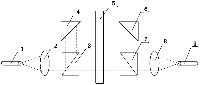
[0019] Such as figure 1 As shown, it is a schematic structural view of the fiber space transmission mode conversion device based on the optical phased array of the present invention, the conversion device consists of a first optical fiber coupling interface 1, a first collimating beam expander 2, and a first beam splitter 3 , a first mirror 4, an optical phased array 5, a second mirror 6, a second beam splitter 7, a second collimator beam expander 8 and a second fiber coupling interface 9, the first fiber coupling interface 1, First collimated beam expander 2, first beam splitter 3, first mirror 4 and second mirror 6, second beam splitter 7, second collimated beam expander 8, second fiber coupling interface 9 The active surface of the optical phased array 5 is symmetrically placed to form a 4-f system. The optical phased array 5 is placed on the Fourier plane of the 4-f system. The optical phased array 5 is used to carry the phase distribution of the design. The beam wave act...

Embodiment 2

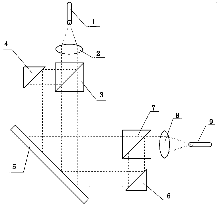
[0021] Such as figure 2 As shown, it is another schematic structural view of the fiber space transmission mode conversion device based on the optical phased array of the present invention, the conversion device consists of a first optical fiber coupling interface 1, a first collimating beam expander 2, a first beam splitter 3. The first mirror 4, the optical phased array 5, the second mirror 6, the second beam splitter 7, the second collimator beam expander 8 and the second fiber coupling interface 9, the first fiber coupling interface 1 , the first collimated beam expander 2, the first beam splitter 3, the first mirror 4 and the second mirror 6, the second beam splitter 7, the second collimated beam expander 8, the second fiber coupling interface 9 is symmetrically placed on the vertical plane of the active surface of the optical phased array to form a 4-f system. The optical phased array 5 is placed on the Fourier plane of the 4-f system, and the optical phased array 5 is u...

Embodiment 3

[0023] Utilize the optical-based A phased array optical fiber space transmission mode conversion device realizes a method for optical phased array optical fiber space transmission mode conversion.

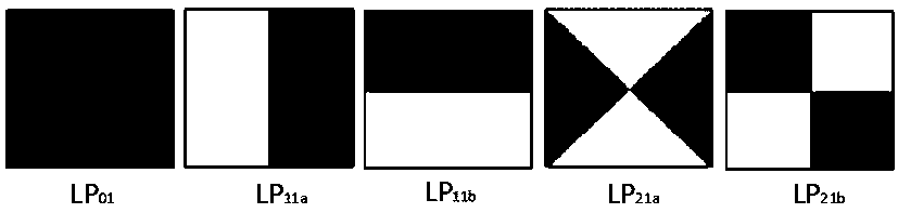
[0024] Step 1: Set the spatial transmission mode of the optical fiber connected to the first optical fiber coupling interface 1, and the LP in the single-mode optical fiber connected to the first optical fiber coupling interface 1 01 Mode, the spatial transmission mode required by the access fiber at the second fiber coupling interface 9, that is, converted into the LP that is connected to the few-mode fiber at the second fiber coupling interface 9 01 、LP 11 (a), LP 11 (b), LP 21 (a), LP 21 (b) schema such as Figure 4 Shown, LP 01 、LP 11 (a), LP 11 (b), LP 21 (a), LP 21 (b) refers to the spatial transmission mode of different optical fibers, and the initial phase distribution of the optical phased array is set to no modulation mode;

[0025] Step 2: Determine whether th...


PUM


Abstract

The invention relates to the crossing field of diffraction optics and optical fiber optics, in particular to an optical fiber spatial transmission mode converting device and a converting method based on an optical phased array under free and flexible programmed control. According to the optical fiber spatial transmission mode converting device, two sets of optical fiber coupling interfaces, calibration beam expanders, beam splitters and reflectors are arranged in symmetry with an optical phased array acting surface or the perpendicular surface of the optical phased array acting surface, then a 4-f system is formed, the optical phased array 5 is arranged on the Fourier plan of the 4-f system, and thus the converting device is formed. The invention further discloses a converting method using the converting device. Free and flexible conversion of optical fiber spatial transmission modes is achieved.

Description

technical field [0001] The invention relates to the field of intersecting diffractive optics and fiber optics, in particular to a conversion device and conversion method for multiple transmission modes in fiber space based on an optical phased array that can be freely and flexibly programmed and controlled. Background technique [0002] The multiple transmission modes of optical fiber space are diverse, and are widely used in the fields of optical fiber sensing, optical fiber communication, and optical fiber wearable devices. Most of the space transmission modes are one-to-one mode conversion, that is, "one thing, one use", which cannot meet the needs of free and flexible conversion. Contents of the invention [0003] The technical problem to be solved by the present invention is: how to realize the free and flexible transformation of multiple transmission modes in optical fiber space, and avoid "one thing, one use". [0004] The technical solution adopted in the present ...

Claims


Application Information

Patent Timeline
Patent Type & Authority Patents(China)
IPC IPC(8): G02F1/29H04B10/25
CPCG02F1/292H04B10/2589H04B10/25891
Inventor 王东靳宝全王云才王宇乔铁柱张红娟高妍
Owner TAIYUAN UNIV OF TECH
Why Eureka
Try Eureka