Optical fiber spatial transmission mode converting device and converting method based on optical phased array
An optical phased array and space transmission technology, which is applied in the intersecting fields of diffractive optics and fiber optics, can solve problems such as unsatisfactory free and flexible conversion, and achieve the effect of simple structure and flexible mode conversion
- Summary
- Abstract
- Description
- Claims
- Application Information
AI Technical Summary
Problems solved by technology
Method used
Image
Examples
Embodiment 1
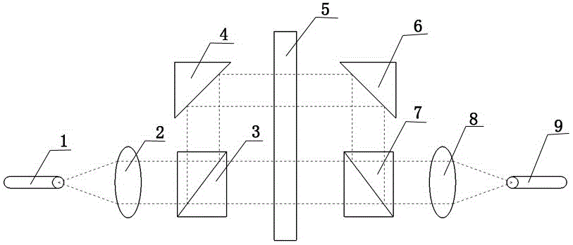
[0019] Such as figure 1 As shown, it is a schematic structural view of the fiber space transmission mode conversion device based on the optical phased array of the present invention, the conversion device consists of a first optical fiber coupling interface 1, a first collimating beam expander 2, and a first beam splitter 3 , a first mirror 4, an optical phased array 5, a second mirror 6, a second beam splitter 7, a second collimator beam expander 8 and a second fiber coupling interface 9, the first fiber coupling interface 1, First collimated beam expander 2, first beam splitter 3, first mirror 4 and second mirror 6, second beam splitter 7, second collimated beam expander 8, second fiber coupling interface 9 The active surface of the optical phased array 5 is symmetrically placed to form a 4-f system. The optical phased array 5 is placed on the Fourier plane of the 4-f system. The optical phased array 5 is used to carry the phase distribution of the design. The beam wave act...
Embodiment 2
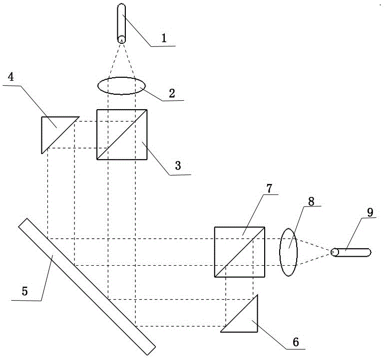
[0021] Such as figure 2 As shown, it is another schematic structural view of the fiber space transmission mode conversion device based on the optical phased array of the present invention, the conversion device consists of a first optical fiber coupling interface 1, a first collimating beam expander 2, a first beam splitter 3. The first mirror 4, the optical phased array 5, the second mirror 6, the second beam splitter 7, the second collimator beam expander 8 and the second fiber coupling interface 9, the first fiber coupling interface 1 , the first collimated beam expander 2, the first beam splitter 3, the first mirror 4 and the second mirror 6, the second beam splitter 7, the second collimated beam expander 8, the second fiber coupling interface 9 is symmetrically placed on the vertical plane of the active surface of the optical phased array to form a 4-f system. The optical phased array 5 is placed on the Fourier plane of the 4-f system, and the optical phased array 5 is u...
Embodiment 3
[0023] Utilize the optical-based A phased array optical fiber space transmission mode conversion device realizes a method for optical phased array optical fiber space transmission mode conversion.
[0024] Step 1: Set the spatial transmission mode of the optical fiber connected to the first optical fiber coupling interface 1, and the LP in the single-mode optical fiber connected to the first optical fiber coupling interface 1 01 Mode, the spatial transmission mode required by the access fiber at the second fiber coupling interface 9, that is, converted into the LP that is connected to the few-mode fiber at the second fiber coupling interface 9 01 、LP 11 (a), LP 11 (b), LP 21 (a), LP 21 (b) schema such as Figure 4 Shown, LP 01 、LP 11 (a), LP 11 (b), LP 21 (a), LP 21 (b) refers to the spatial transmission mode of different optical fibers, and the initial phase distribution of the optical phased array is set to no modulation mode;
[0025] Step 2: Determine whether th...
PUM
 Abstract
Description
Claims
Application Information
 - R&D
- Intellectual Property
- Life Sciences
- Materials
- Tech Scout
- Unparalleled Data Quality
- Higher Quality Content
- 60% Fewer Hallucinations
Browse by: Latest US Patents, China's latest patents, Technical Efficacy Thesaurus, Application Domain, Technology Topic, Popular Technical Reports.
© 2025 PatSnap. All rights reserved.Legal|Privacy policy|Modern Slavery Act Transparency Statement|Sitemap|About US| Contact US: help@patsnap.com


