
Power supply control device

A technology of power control device and current source, applied in measurement device, data processing power supply, measurement flow/mass flow, etc., can solve problems such as system energy waste and achieve the effect of saving energy

Inactive Publication Date: 2016-06-08
WARECONN TECH SERVICE (TIANJIN) CO LTD
View PDF7 Cites 0 Cited by
  • Summary
  • Abstract
  • Description
  • Claims
  • Application Information

AI Technical Summary

Problems solved by technology

But sometimes, the customer usually only uses one CPU and one group of memory, but the voltage regulator of the non-working CPU and other groups of memory is still working, and the voltage regulator cannot control its own shutdown or startup according to whether there is a load or not. , which leads to a waste of system energy

Method used


Image

  • Power supply control device
  • Power supply control device

Examples


Embodiment Construction

[0010] Below in conjunction with accompanying drawing and preferred embodiment the present invention is described in further detail:

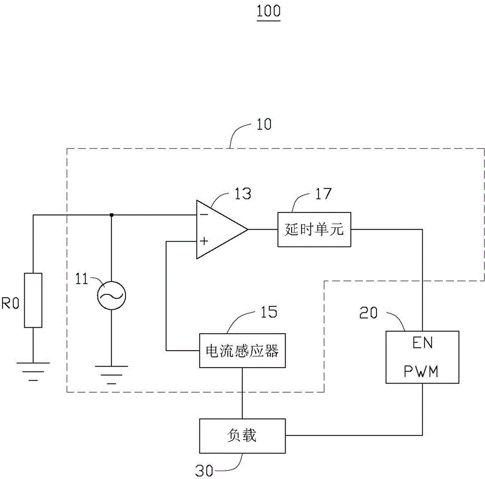
[0011] Please refer to figure 1 , the power control device 100 of the present invention includes a resistor R0 and a voltage regulation module 10 . The voltage regulation module 10 is located in the pulse width modulation integrated circuit of the voltage regulator, and the resistor R0 is disposed outside the voltage regulation module 10 .

[0012] The voltage regulation module 10 includes a current source 11 , a comparator 13 , a current sensor 15 , and a delay unit 17 . The resistance R0 and the current source 11 include a first end and a second end respectively, the first ends of the resistance R0 and the current source 11 are connected to the inverting input end of the comparator 13, the resistance R0 and the current source 11 Both ends are grounded. The current source 11 is used to provide a working current for the resistor R0. The inv...


PUM


Abstract

A power supply control device comprises a resistor and a voltage regulation module; the voltage regulation module comprises a comparator, a current source, a current inductor and a control unit; the control unit is connected with a drive chip so as to receive a modulation signal; an inverted input end of the comparator is connected with a first end of the resistor and a first end of the current source so as to receive a first voltage signal; a non-inverting input end of the comparator is connected with the current inductor so as to receive a second voltage; the output end of the comparator is connected with the control unit; when the first voltage is smaller than the second voltage, the comparator sends a high level control signal to the control unit, and the control unit sends the modulation signal to a load; when the first voltage is bigger than or equal to the second voltage, the comparator outputs a low level control signal to the control end of the control unit, and the control unit stops sending the modulation signal to the load.

Description

technical field [0001] The invention relates to a power control device. Background technique [0002] Mainstream server products are configured with two CPUs and four sets of memory. On most applications, the CPU and memory will fill up. But sometimes, the customer usually only uses one CPU and one group of memory, but the voltage regulator of the non-working CPU and other groups of memory is still working, and the voltage regulator cannot control its own shutdown or startup according to whether there is a load or not. , which leads to a waste of system energy. Contents of the invention [0003] In view of the above, it is necessary to provide a power control device that can turn off the voltage regulator when the system is working without load. [0004] A power control device, comprising: a resistor and a voltage regulation module, the voltage regulation module includes a comparator, a current source, a current sensor, the current sensor is connected to a load, the res...

Claims


Application Information

Patent Timeline
Patent Type & Authority Applications(China)
IPC IPC(8): G06F1/32G06F1/26
Inventor 潘亚军
Owner WARECONN TECH SERVICE (TIANJIN) CO LTD
Learn More